page 18 of 44 M.1k2 Hardware Guide - Version 1.3
CHAPTER 4: Operation
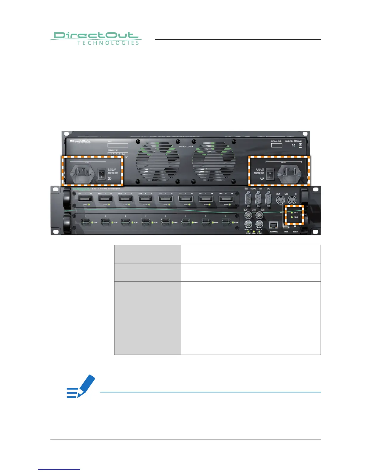
The green LEDs (PSU 1 & PSU 2) indicate that a working power supply is
connected to the power supply unit. Note that an unlit LED does not guarantee
that the device is free of voltage. To ensure that the device is completely
disconnected from mains voltage, the power chords must be disconnected.
CHAPTER 4: Operation
Introduction
This chapter describes the basic operation of the device.
Global Control
The control on the right of the front panel indicates the power supply. Power
switches are on the back panel:
PSU 1 & PSU 2 (rear) 2 Switches
Enable / disable power supply.
PSU 1 & PSU 2 (rear) C13 socket
Connect the power supply here (84 - 264 V AC).
PSU 1 & PSU 2 (front) 2 LEDs (green): indicate the status of both
power supply units
LED OFF = Power supply inactive
LED ON = Power supply active
LED blinking
4 times per second = The power supply was active,
and is now inactive. Whether
this is a fault state depends
on the circumstances.
If both PSU LEDs are blinking and the fan is blowing at full speed, the FPGA is
being programmed. This only happens during reboot after an update.
NOTE!