6 / 21
The power wires must remain between 1 mm² (17 AWG) and 1.5 mm² (16 AWG). Make sure the cable performances suit the connected
loads.
Operating, handling, or servicing this product must be achieved by a qualified operator. Turn off power before any kind of servicing.
Input Wiring
Each controller has physical connections for six (6) inputs (marked as UIx for Universal Inputs, DIx for Digital Inputs, and SIx for Sensor Inputs). All in-
puts must be configured properly in EC-
gfx
Program to ensure proper input readings.
All input wiring must be connected using the provided detachable connectors.
Before connecting a sensor to the controller, refer to the installation guide of the equipment manufacturer.
Connectors allow the use of cables up to 1.5 mm² (16 AWG).
UI SI DI
Digital Inputs
Voltage Inputs
Resistive Inputs
Pulse Inputs
Table3:
Input Configuration Capabilities
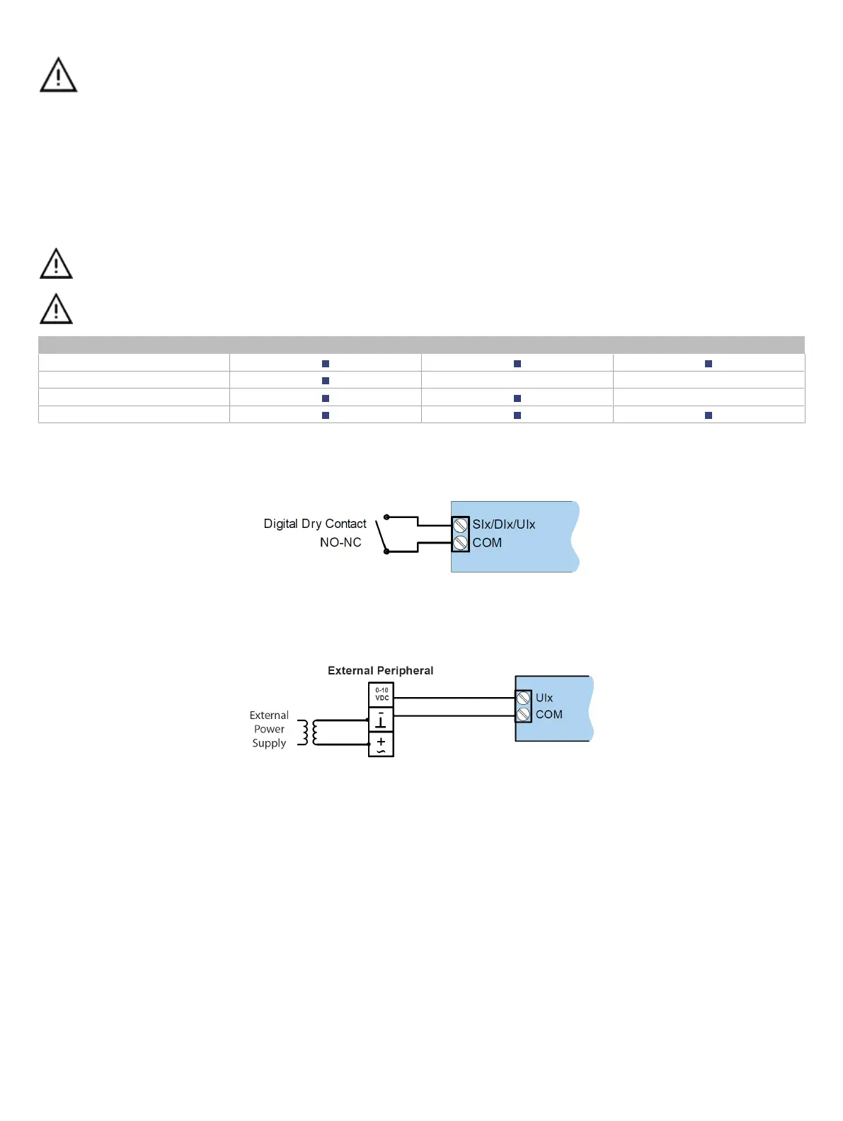
Wiring Digital Inputs (Six – Dix – Six)
This input configuration is used to monitor digital dry contacts.
Figure7: Digital input - Dry contact (NO & NC)
Wiring Voltage Inputs (UIx)
Voltage inputs have a range of 0 to 10 Vdc. Connect the voltage input according to the following figure. The transducer used must be powered externally.
Figure8: Voltage input – 3-wire transducer with its own power source
 Loading...


