3 / 21
General Wiring Recommendations
Turn off power before any kind of servicing.
£ All wiring must comply with electrical wiring diagrams as well as national and local electrical codes.
£ To connect the wiring to a device, use the terminal connectors. Use a small flat screwdriver to tighten the terminal connector screws once the wires
have been inserted (strip length: 0.25’’ (6mm), maximum tightening torque 0,4 Nm (3.45 in-lb)).
£ Comply with all network and power supply guidelines outlined in the Network Guide.
£ Power type cables (i.e. for power, 3-wire voltage and current inputs and outputs) should be kept apart from other types of wiring to avoid any ambi-
ent noise transmission to other wires.
£ Do not connect the universal inputs, analog/digital outputs or common terminals to earth or chassis ground (unless stated otherwise).
£ Keep all wires away from high speed data transmission cables (for example, Ethernet, etc.).
£ Keep input and output wiring in conduits, trays or close to the building frame if possible
£ Conductors must be made inaccessible and wiring must comply with local wiring regulations and methods appropriate for fixed equipment installa-
tion in a building.
£ Installation must be carried out in a fashion such that double insulation integrity is maintained.
Mounting Instructions
Each controller can be mounted on a DIN rail to speed up the installation procedure. The controllers are also equipped with four mounting holes 0.28” x
0.15” (7.2 mm x 4 mm), and they can be mounted in panel or on a wall by using the appropriate screw types (use sheet metal, thread forming, or self-
tapping screws accordingly).
If the controller is to be installed out of an electrical box, it is necessary to use the optional strain-relief and terminal block cover (refer to the Strain Relief
and Terminal Block Cover section for further information).
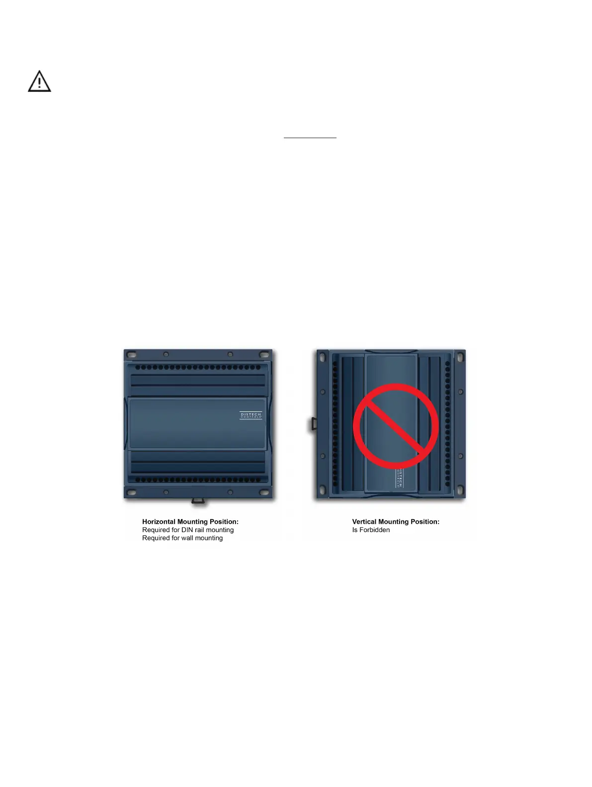
The controller’s mounting orientation must be horizontal with controller’s back attached to a vertical wall surface.
Figure2: Permitted Mounting Positions

 Loading...


