10 / 21
Wiring Analog Outputs (AOx)
Analog outputs can be configured to provide either a discrete signal of 0 or 12 VDC or a linear signal ranging from 0 to 10 VDC. The discrete signal can
be used to generate a pulse wave modulation (PWM) signal or a simple two-state signal.
Analog output connectors accept wires between 0.75 mm² (18 AWG) and 1.5 mm² (16 AWG).
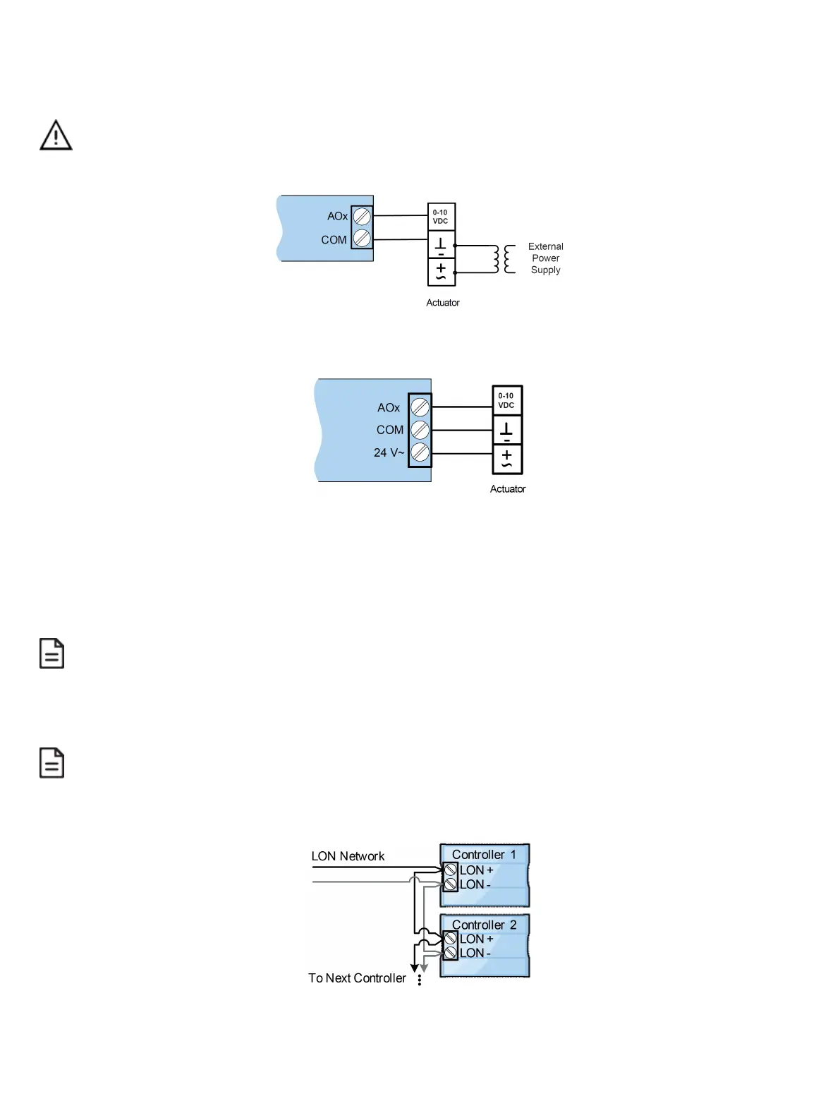
If an analog actuator is being controlled, connect the 0 to 10 VDC output, along with an external 24 VAC power source, to the analog actuator according
to the following figure.
Figure21: Self-powered 0-10 V actuator wiring
The onboard 24 VAC power supply can be used to power 0-10 V actuators according to the following figure (ECL-PTU-208 and ECL-PTU-308 only):
Figure22: Controller-powered 0-10 V actuator wiring
Communications Wiring
The recommended cable type for LONWORKS
®
communications is 22AWG (0.65 mm), twisted pair, unshielded. The LONWORKS communication wire is po-
larity insensitive and can be laid out in a bus, star, loop or free topology. For loop topology, polarity is important, special care must be taken when con-
necting the LONWORKS network to avoid short circuit.
It is recommended to use the bus topology network configuration for all LONWORKS communication wiring, as it allows
for easy network troubleshooting.
Connect both wires to the LON+ and LON‑ terminals of the controller. If inserting multiple wires in the terminals, ensure to properly twist wires together
prior to inserting them in the terminal connectors.
For more information and detailed explanations on network topology and wire length restrictions, refer to the Network Guide. It can be downloaded from
our website.
It is important to use proper network terminators depending on the type of network topology used. Failure to do so
may result in communication errors between controllers.
For a bus topology, 2 network terminators are required (1 at each end of the bus topology channel). For a free topology, 1 network terminator is required
and it can be put anywhere on the channel.
Figure23: Communications Wiring
 Loading...


