16
IP1776EN 2012-02-20
13. EXAMPLE APPLICATION FOR UP-AND-OVER DOORS WITH IN-PARALLEL
MOTORS
M1
36 35 34 33 32 31
24V=
Motor 1
24V=
Motor 2
+
-
+
-
OM
OM=OFF
S1=ON
S2=ON
S3=ON
S4=OFF
M1<MAX
M1
(VM)
M1
(VM)
max 10 s
OPENING CLOSING
S1
S2
S3
S4
M1
36 35 34 33 32 31
24V=
Motor 1
24V=
Motor 2
+
-
+
-
OM
OM=OFF
S1=ON
S2=ON
S3=ON
S4=OFF
M1=MAX
VM
VM
max 10 s
OPENING CLOSING
S1
S2
S3
S4
A
A
C
C
max
10 s
1N4007
OM
FC
FC=OFF
OM=OFF
M1
36 35 34 33 32 31
24V=
Motor 1
24V=
Motor 2
+
-
+
-
S1=ON
S2=ON
S3=ON
S4=OFF
M1<MAX
M1
(VM)
M1
(VM)
OPENING CLOSING
S1
S2
S3
S4
A
A
C
C
max
10 s
1N4007
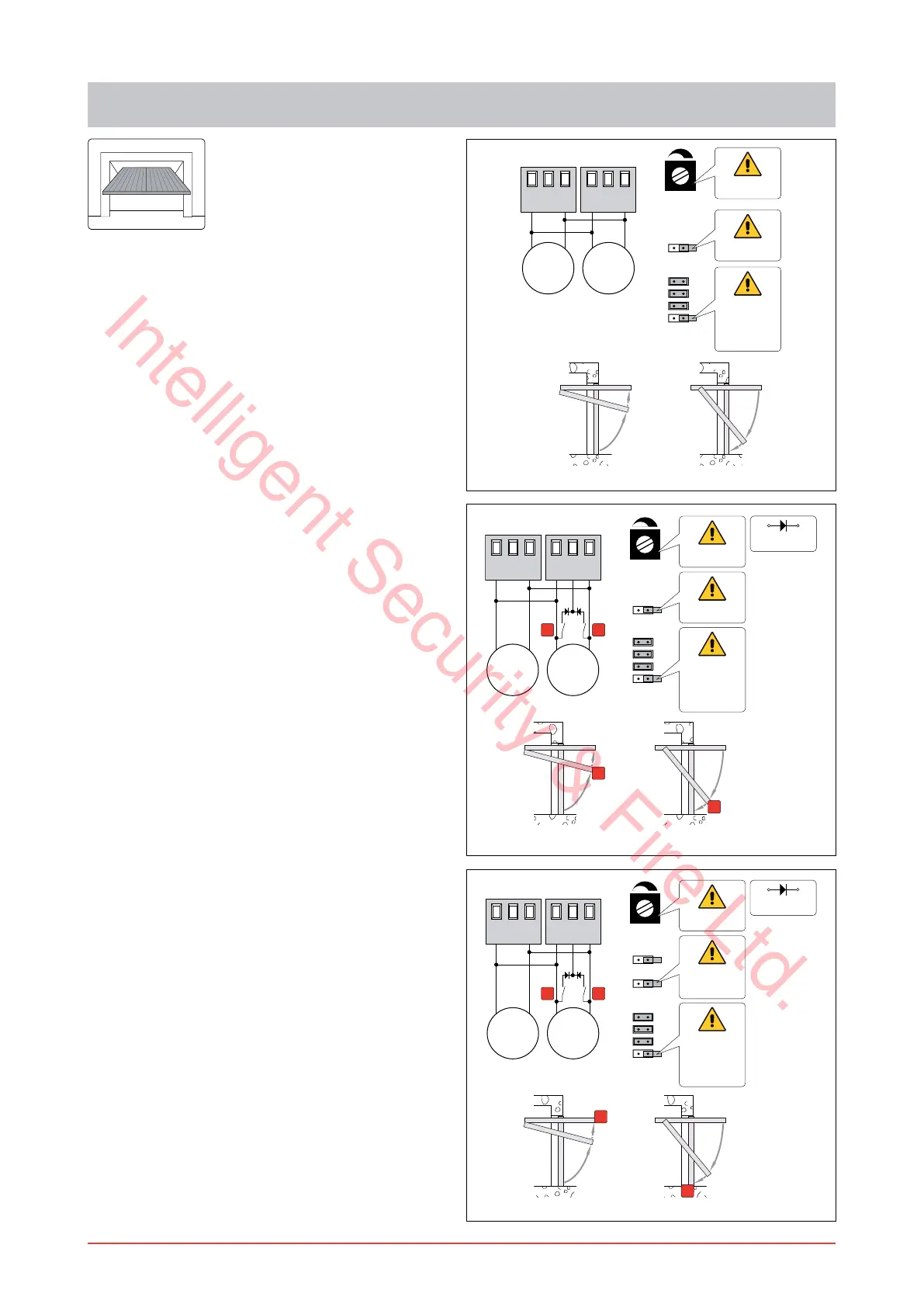
When the control panel is used in applications for au-
tomations with up-and-over doors with two parallel
motors, these connections can be made:
(Fig. 13.1) Use without limit switches.
Set OM=OFF.
Connect the motors as shown in the ¿gure.
NOTE: during the opening operation, the polarities
are those indicated in the ¿gure.
Set VM to the desired speed.
Set M1 so as to obtain slow down of the door wing
before the mechanical stop.
With the above connections the wing stops on the
opening and closing mechanical stop.
When the time set with M1 runs out:
on opening operation the slow down time is a
maximum of 10 s;
on closing operation the wing slows down until it
reaches the mechanical stop.
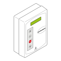
(Fig. 13.2) Use with slow down limit switches.
Set OM=OFF.
Connect the motors and slow down limit switches
as shown in the ¿gure:
>A@ opening slow down limit switch;
>C@ closing slow down limit switch.
Set M1=MAX. Set VM to the desired speed.
With the above connections the wing stops on the
opening and closing mechanical stop.
After the slow down limit switch has been triggered
on opening operation and on closing operation the
maximum slow down time is 10 s.
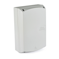
(Fig. 13.3) Use with stop limit switch.
Set OM=OFF and FC=OFF.
Connect the motors and stop limit switches as
shown in the ¿gure:
>A@ opening stop limit switch;
>C@ closing stop limit switch.
NOTE: a single limit switch can also be installed.
Set M1<MAX. Set VM to the desired speed.
Set M1 so as to obtain slow down of the door wing
before the limit switch is triggered.
With the above connections, the wing stops when
the limit switch operates.
When the time set with M1 runs out:
on opening operation the slow down time is a
maximum of 10 s;
on closing operation the wing slows down until it
reaches the stop limit switch.
Fig. 13.1
Fig. 13.2
Fig. 13.3
Intelligent Security & Fire Ltd.