1592001850 XC660D GB r3.4 04.09.2017.docx XC660D 10/55
Their functions are set by the parameter iF07 and iF08 respectively.
They can be used for liquid level monitoring, activate the energy saving function or silence mode
from a external devices.
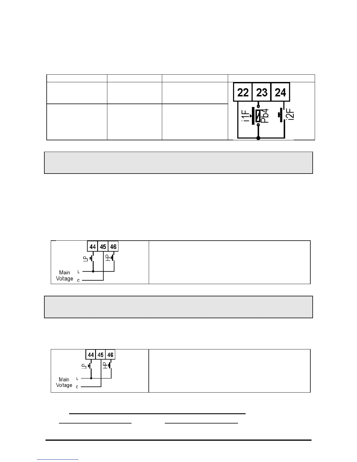
The digital input connection is explain in the following table
DI7 configurable
input/Probe 4
iF07: function
iP07: polarity
iF08: function
iP08: polarity
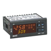
5.7 Circuit with 1 SUCTION and 1 CONDENSER: HP – LP
Pressure switch connections
!!!WARNING: controller is provided with both free voltage digital inputs, and main voltage
inputs.!!!!
NOTE: The main voltage inputs are designed only for HP and LP pressure switches.
The low pressure switch has to be connected to the terminal 45 (common) and 46 (line)
The high pressure switch has to be connected to the terminal 45 (common) and 44 (line)
as shown on the following wiring diagram.
NOTE: the main voltage is related to the voltage supply
of the controllers.
Models at 115V or 230V the inputs operate at 115 or
230V.
Models at 24V the inputs operate at 24V.
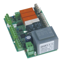
5.8 Circuit with 2 SUCTIONS and 1 CONDENSER: HP – LP
Pressure switch connections
In case of racks with 2 suction circuits and 1 condenser the LP1, low pressure switch, and HP
high pressure switch, must be connected to the terminals 44-45 and 45-46 as explained in the
following wiring diagram
NOTE: the main voltage is related to the voltage supply
of the controllers.
Models at 115V or 230V the inputs operate at 115 or
230V.
Models at 24V the inputs operate at 24V.
5.8.1 Suction 2: connection of the Low Pressure switch,
The LP2 low pressure switch of circuit 2, must be a free of voltage signal.
To manage it, set:
i8F = LP2 and then connect it to the terminals 22-24.