Do you have a question about the dixell XC660D and is the answer not in the manual?
Verify the software release of the XC660D controller for manual compatibility.
Emphasizes reading the manual for correct instrument usage and safety.
Essential safety measures to follow before and during instrument operation.
Details about pressure transducers for the XC660D, including models and ranges.
Information on the NP4-67 temperature probe for discharge temperature monitoring.
Important safety guidelines and precautions before making electrical connections.
Diagrams and details for connecting loads, probes, and power supply to the controller.
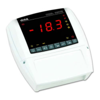
Instructions for connecting the VC660 remote keyboard to specific XC660D models.
Details on connecting pressure and temperature probes, emphasizing polarity and wiring.
Details on connecting external contactors for loads to the controller's relays.
Configuration of digital inputs for safety functions and load monitoring.
Wiring for connecting HP/LP pressure switches in single suction systems.
Wiring for HP/LP pressure switches in systems with two suction circuits.
Instructions and dimensions for mounting the VC660 remote keyboard.
Procedure for setting the refrigerant type parameter (FtyP) for accurate operation.
Steps to configure pressure probe ranges (PA04, PA20, FA04, FA20).
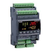
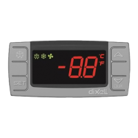
Explanation of the controller's upper and lower display information.
Description of the function of each key on the controller's keypad.
Explanation of the meaning of various LED indicators and icons on the controller.
Procedure to view the current set points for compressors and fans.
Step-by-step guide to changing compressor and fan set points.
Steps to access the user-accessible parameter list (Pr1).
Procedure to access the protected parameter list (Pr2) using a security code.
General procedure for modifying parameter values within the programming mode.
Steps to disable an output for maintenance, excluding it from regulation.
Procedure to view the accumulated running hours for each load.
Procedure to access and view logged alarms and their details.
Instructions to lock the keypad, preventing accidental changes.
Procedure to copy controller settings to a Hot Key device.
Procedure to load settings from a Hot Key device to the controller.
Parameters for configuring the system layout and regulation type (compressors/fans).
Settings for configuring various pressure and temperature probes.
Configuration of digital inputs (iF01-iF08) for various safety and control functions.
Settings for display units (temperature/pressure) and measurement scales.
Parameters for compressor regulation, including proportional band and neutral zone.
Parameters for fan regulation, including proportional band and energy saving.
Parameters related to compressor alarms (pressure, temperature, delays).
Parameters for fan alarms (pressure, temperature, delays).
Parameters for monitoring and managing suction superheat in circuit 1.
Configuration for the first optional analog output.
Configuration for the second optional analog output.
Regulation strategy for compressors with identical capacity using dead band control.
Control strategy for compressors with different capacities.
Details on regulating screw compressors using multiple valves.
Configuration for fans driven by inverters or ECI, using analog output.
Using analog output to link to a temperature probe for free scaling.
Using digital inputs to verify compressor operation and detect failures.
Function to prevent liquid flooding by disabling injection when compressors are blocked.
Monitoring suction superheat to protect compressors from low superheat conditions.
Managing a hot gas injection valve to increase suction superheat.
Categorization of alarms and their signaling methods.
Alarms related to electronic pressure switches for suction sections.
Alarms for pressure switches in suction and condensing sections.
Alarms for compressor and fan safety inputs (e.g., oil, overheating).
Alarms indicating failure of temperature or pressure probes.
Alarms for high/low pressure or temperature deviations in compressor/fan sections.
How to silence the audible alarm buzzer.
A table summarizing various alarm codes, causes, actions, and resets.
Default set point for compressors.
Default set point for compressor circuit 2.
Default set point for fans.
| Model | XC660D |
|---|---|
| Output Type | Relay |
| Number of Outputs | 6 |
| Display | LCD |
| Buzzer | Yes |
| Remote display | Optional |
| Type | Controller |
| Power Supply | 24V AC/DC |
| Hot Key | Yes |
| Protection grade | IP20 |