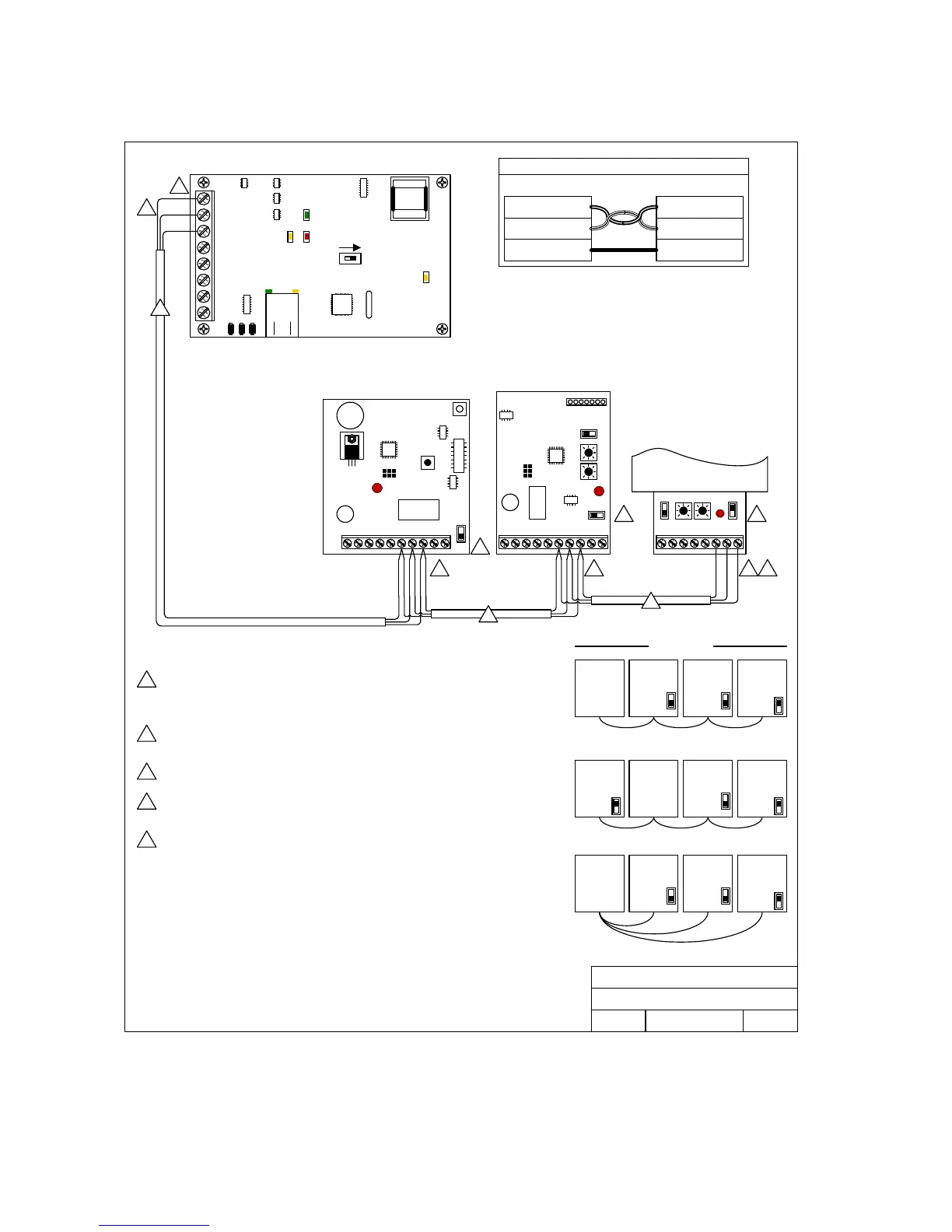
RS-485 Connections
SW3SW2SW4
11121316 15 1417
12345678910
OFF
DOORKING, INC., INGLEWOOD, CA 90301
Date: Dwg. No. Rev.
Title:
6/09
A
M1812AP-002
1812 Access Plus
RS-485 wire connections.
1
1
3
2
5 5
The wires connecting terminals 7 & 8 between RS-485 boards MUST be twisted. We
recommend that you use Cat5e cable. Use one pair to connect terminals 7 & 8, and then one
wire from the other pairs to connect terminal 6.
Termination switch is in the OFF position for middle units, and in the ON position for end units.
If terminals 6, 7 & 8 have two wires connected to them, the termination switch must be OFF. If
terminals 6, 7 & 8 have only a single wire connected, the termination switch must be ON.
Each RS-485 device (keypad, card
reader, receiver) must have a
unique address, starting with 003.
Do not skip addresses. The order
in which the device addresses are
connected to the 1812 does not
matter. What is important is that
the addresses must be in
sequence, starting with 003.
2 4
Maximum distance from end to end is 4000 feet in a Daisy Chain format as shown.
Correct
1812
Controller
OFF
Address 004
ON
Address 005
End Unit
Term Sw ON
1812
Controller
Address 003
OFF OFF
Address 004
ON
Address 006
3
3
MASTER CODE
12345678910
OFF
Keypad
Address 003
Card Reader
Address 004
MicroPlus Receiver
Address 005
4000 Ft. Maximum
1812
Controller
OFF
Address 004
ON
Address 003
ON
Address 005
Correct
Wrong!
5
Valid device addresses for use
with the 1812 Access Plus system
are 003, 004, 005, 006, 007 and 008.
The device address is referred to
as a relay number in the
programming software. The relays
on the 1812 circuit board are 001
and 002.
In this example, the keypad is
relay 003, the card reader is relay
004 and the MicroPlus Receiver is
relay 005.
SW3SW2SW4
12345678
ON
SW5
The 1812 system does not have to be on the end of the Daisy Chain wiring scheme. What is
important is that the distance restriction (4000 Ft.) be observed and that the devices at the end
of the chain have their termination switch turned ON.
The wires connecting terminals 1 & 2 from the 1812 Access Plus to terminals 8 & 7 on the RS-
485 boards MUST be twisted. We recommend that you use Cat5e cable. Use one pair to
connect these terminals (terminal 1 connects to terminals 8; terminal 2 connects to terminals 7)
and then one wire from the other pairs to connect the common terminal (terminal 3 from the
1812 Access Plus to terminals 6 on the RS-485 boards).
2 2
If wiring will be outdoors or underground, use Cat5e Gel Filled (flooded) UV Resistant Direct
Burial Cable.
3
4
4
5
Terminal 1 from the Access Plus board connects to RS-485 board(s) terminal 8.
Terminal 2 from the Access Plus board connects to RS-485 board(s) terminal 7.
Terminal 3 from the Access Plus board connects to RS-485 board(s) terminal 6.
Wires connecting terminals 1 & 2 to terminals 8 & 7 MUST be twisted.
Term 8
RS-485 Data A (+)
Term 6
RS-485 Common
Term 7
RS-485 Data B ( - )
Term 1
RS-485 Data A ( + )
Term 2
RS-485 Data B ( - )
Term 3
RS-485 Common
Access Plus Board RS-485 Board
RS-485 Terminal Connections
ON
SW1 MODEM / TCP ENB
1
2
3
4
5
6
7
8
BAD DNS
RS-485 RX
LAN DOWN
Phone Line
In Use
LAN
Connection
Data
Transmit
Address 003
OFF
Middle Unit
Term Sw OFF
End Unit
Term Sw ON
Middle Unit
Term Sw OFF
Middle Unit
Term Sw OFF
Middle Unit
Term Sw OFF
End Unit
Term Sw ON
Middle Unit
Term Sw OFF
End Unit
Term Sw ON
Page 22 1812-162-B-6-09