Getting Started
Page 9
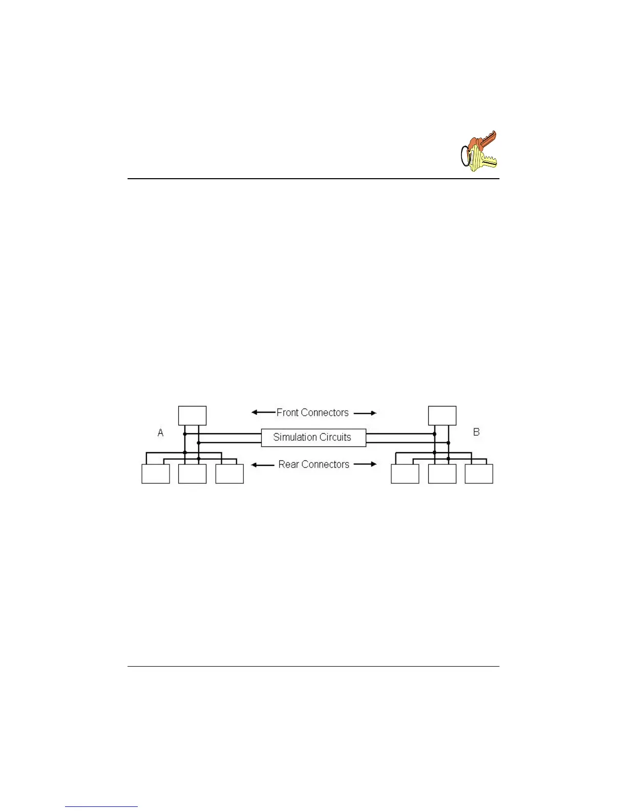
3.2 Connecting the DLS 50
The side A of the simulated wireline can be accessed from any of the RJ-45 connectors
labelled "A" at the front or at the back of the DLS 50, or from the terminal blocks at the
back of the DLS 50. The user can also inject impairments to side A of the wireline by
using the "noise" RJ-45 connector on the back of the DLS 50.
Side B of the simulated wireline can be accessed from any of the RJ-45 and terminal
blocks labelled "B" as explained above.
Note that all the RJ-45 connectors and terminal blocks on each side are connected in
parallel.
The DLS 50 provides a fully bi-directional wireline simulation.
Fig. 3.4 DLS 50 internal connection paths
3.3 Changing the Cable Length
The unit can be controlled via the 4 arrow keys on the front panel. The left and right
arrow keys select the digit to be set, and the up and down keys select the value of that
digit. When reaching the maximum or the minimum, the value stops changing. The
display will show the current length of the simulated cable, the type of wireline, and the
maximum length shown on the right bottom section of the screen.