Digital Monitoring Products XR500 Series Installation Guide
8
INSTALLATION
4.2 Mounting Keypads and Zone Expansion Modules
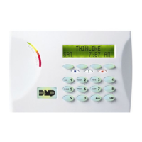
DMP LCD keypads have removable covers that allow you to easily mount the keypad to a wall or other at surface
using the screw holes on each corner of the base. Before mounting the base, connect the keypad wire harness leads
to the keypad cable from the panel and to any device wiring run to that location. Then attach the harness to the pin
connector on the PC board, mount the base, and install the keypad cover making sure all of the keys extend through
their respective holes.
For mounting keypads on solid walls, or for applications where conduit is required, use the Model 695 1-1/2” deep or
the Model 696 1/2” deep backboxes.
The DMP 711, 712-8, 714, 715, 716, and 717 modules are each contained in molded plastic housings with removable
covers. The base provides you with mounting holes for installing the unit to a wall, switch plate, or other surface.
4.3 Connecting LX-Bus and Keypad Bus Devices
Several factors determine the DMP LX-Bus™ and keypad bus performance characteristics: the wire length and gauge
used, the number of devices connected, and the voltage at each device. When planning an LX-Bus™ and keypad bus
installation, keep in mind the following information:
1. DMP recommends using 18 or 22-gauge unshielded wire for all keypad and LX-Bus circuits. Do not use twisted
pair or shielded wire for LX-Bus and keypad bus data circuits.
2. On keypad bus circuits, to maintain auxiliary power integrity when using 22-gauge wire do not exceed 500
feet. When using 18-gauge wire do not exceed 1,000 feet. To increase the wire length or to add devices, install
an additional power supply that is listed for Fire Protective Signaling, power limited, and regulated (12 Vdc
nominal) with battery backup.
Note: Each panel allows a specic number of supervised keypads. Add additional keypads in the unsupervised
mode. Refer to the panel installation guide for the specic number of supervised keypads allowed.
3. Maximum distance for any one bus circuit (length of wire) is 2,500 feet regardless of the wire gauge. This
distance can be in the form of one long wire run or multiple branches with all wiring totaling no more than
2,500 feet. As wire distance from the panel increases, DC voltage on the wire decreases. Maximum number of
LX-Bus devices on the rst 2,500 foot circuit is 40 devices.
4. Maximum voltage drop between the panel (or auxiliary power supply) and any device is 2.0 Vdc. If the voltage
at any device is less than the required level, add an auxiliary power supply at the end of the circuit. When
voltage is too low, the devices cannot operate properly.
For additional information refer to the LX-Bus/Keypad Bus Wiring Application Note (LT-2031).
Expansion Interface Cards (Models 481, 462N, 462P, 463C, 464-263C and 464-263H)
The LX-Bus provided on these cards requires only a 4-wire cable between the card and any devices connected to the
bus. You can connect devices (zone or output expansion modules) together on the same cable or provide separate
runs back to the card. Each LX-Bus provides up to 100 zones or outputs.
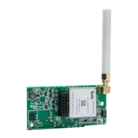
4.4 Wireless Keypad Association
Enable Wireless Keypad Association operation on both the keypad and panel.
To enable association operation in the keypad, access the Installer Options Menu (3577
(INST)) and select RF Survey). The keypad logo LEDs turn on Red until association is
successful.
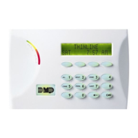
To enable association operation in the XR500 panel, reset panel 3 times within 12
seconds. Allow the keypad bus Transmit/Receive LEDs to turn back on between each
reset.
For 60 seconds the panel listens for wireless keypads that are in the Installer Options
Menu (3577 CMD) and have not been programmed, or associated into another panel. Those keypads are assigned to
the rst open device position automatically based upon the order in which they are detected. The keypad logo turns
Green to indicate it has been associated with the panel.
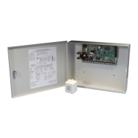
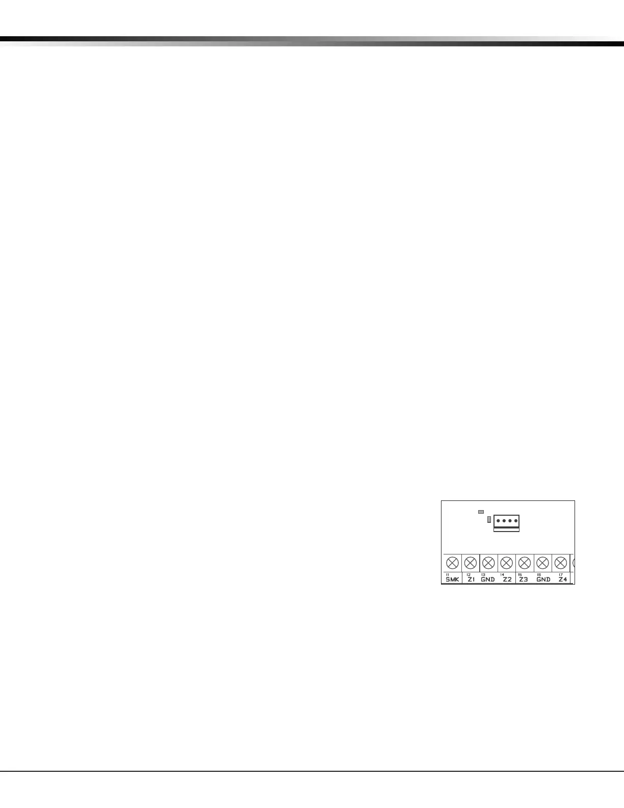
Programming
J8
XMIT
Figure 5: Keypad Bus LEDs
 Loading...