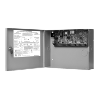
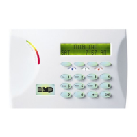
XR500 Series Installation Guide Digital Monitoring Products
23
COMPLIANCE
Listed Compliance Specications
20.1 Introduction
For applications that must conform to a local authorities installation standard or a National Recognized Testing
Laboratory certicated system, please see the following sections.
Universal Burglary Specications
21.1 Introduction
The programming and installation specications contained in this section must be completed when installing the
XR500 Series panel in accordance with any of the burglary standards. Additional specications may be required by a
particular standard. See the XR500 Series Programming Guide (LT-0679).
21.2 Wiring
All wiring must be in accordance with NEC, ANSI/NFPA 70, ANSI/UL 681, and ANSI/UL 827 for all burglary
installations. All transformer wires must be installed in conduit.
21.3 Transformer
The total combined Auxiliary and Bell outputs cannot exceed 1.3 Amps with a 50 VA Transformer. The total combined
Auxiliary and Bell outputs cannot exceed 1.9 Amps with a 56 VA Transformer.
21.4 Control Outside of Protected Area
A Potter EVD or Sentrol 5402 should be used in place of a lined cabinet when the panel is installed outside of the
protected area. Front and rear tamper switches are required. Refer to the system wiring diagram.
21.5 Police Station Phone Numbers
The digital dialer telephone number programmed for communication must not be a police station phone number.
21.6 Bypass Reports
The Bypass Reports option must be programmed as YES for all listed burglary applications.
21.7 System Maintenance
To ensure continuous satisfactory operation of any alarm system, proper installation and regular maintenance by
the installing alarm company and frequent testing by the end user is essential. Oering a maintenance program and
acquainting the user with the correct procedures for system use and testing is also the responsibility of the installing
alarm company.
21.8 Listed Receivers
Operation has been veried with the DMP SCS-VR and SCS-1R receivers and any Central Station Receiver that accepts
industry standard Contact ID (DTMF) format. It is the installer’s responsibility to verify compatibility between the
panel and the receiver used during installation. The installer shall verify the compatibility of the receiver and the
system on a yearly basis.
21.9 Power Supply Supervision
For commercial burglary applications the power supply for all local bells shall be under 24-hour protection. Refer to
the Secondary Power Supply section in this document.
21.10 Wireless Tamper
The Zone Information Disarmed Open Message to Transmit must be programmed Trouble (T). (Not applicable to ANSI/
UL 1023).
21.11 Wireless External Contact
When used, the External Contact of 1101 or 1102 must be programmed Normally Closed.
21.12 Wireless Supervision Time
The Zone Information Supervision Time cannot be set to 0 (zero).
21.13 Detect Wireless Jamming
The Detect Wireless Jamming option must be programmed YES. (Not applicable to ANSI/UL 1023).
21.14 Standby Batteries
Use battery Models 365 (12 Vdc 9Ah), 366 (12 Vdc 18Ah), 368 (12 Vdc 5.0Ah), and 369 (12 Vdc 7Ah) with the XR500
panel when installed in the 341, 350, 350A, or 352 enclosures. The Model 364 (12Vdc 1.3Ah) battery is for use with
the XR500 panel when using the 341 enclosure with the optional 341B Battery Bracket. The Model 364 battery is
rated for 4 hours of standby time.
 Loading...
