DOLD GMBH Operating instructions DMP 96 A
DMP 96 A Version: 020 Number of pages: 26
H0e020bA4.doc Edition: 07.11.2006
24
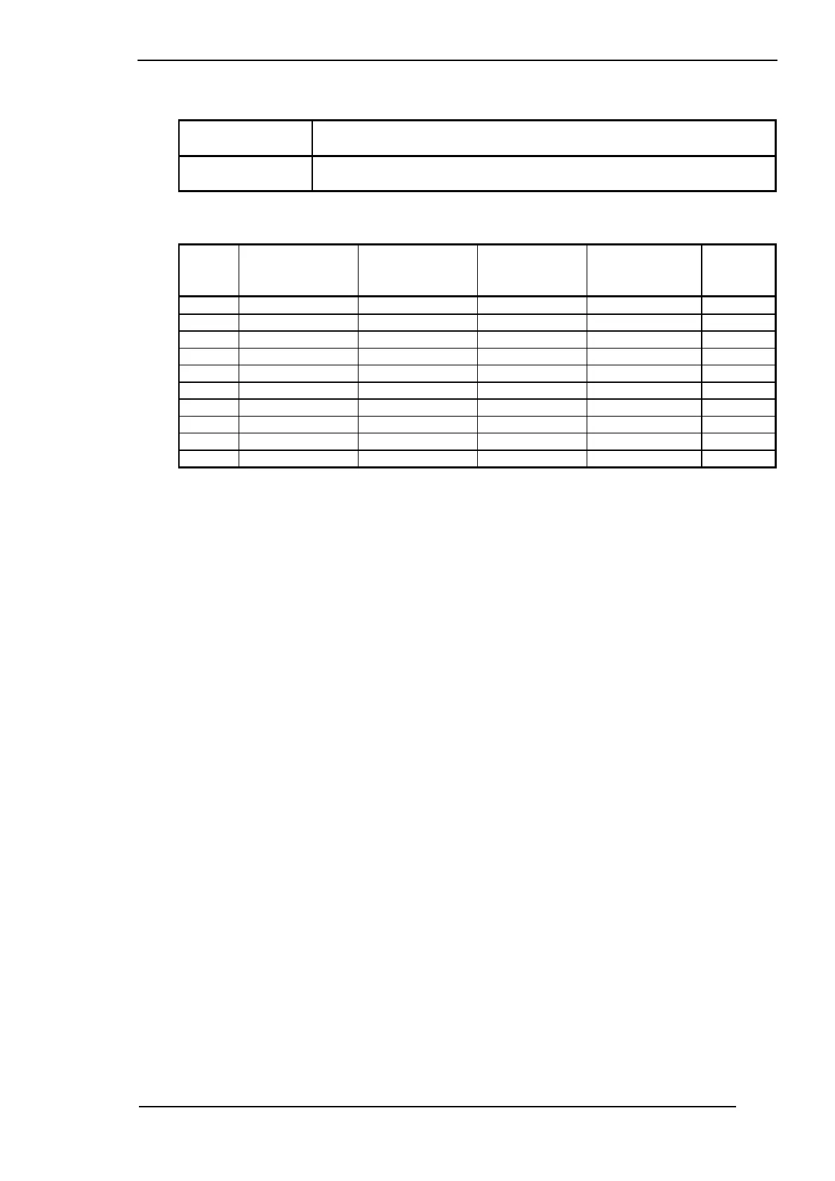
Display: Parameter:
"SEn" Sensor ID as in table
Sensor ID:
Sensor
ID:
ID by ordering
key:
Sensor: Max. display
range:
Max. setpoint
range:
Display:
P 1 P 1 Pt 100 -69...149°C -50...100°C 3 digits
P 2 P 2 Pt 100 -69...249°C -50...200°C 3 digits
P 3 P 3 Pt 100 -69...349°C -50...300°C 3 digits
P 4 P 4 Pt 100 -69...699°C -50...600°C 3 digits
P 5 P 5 Pt 100 -169...149°C -150...100°C 4 digits
tL1 L 1 Fe-CuNi Type L -24...499°C 0...450°C 3 digi ts
tL2 L 2 Fe-CuNi Type L -24...899°C 0...850°C 3 digi ts
tn1 K 1 Ni Cr-Ni Type K -24...649°C 0...600°C 3 dig its
tn2 K 2 Ni Cr-Ni Type K -24...1299°C 0...1200°C 4 d igits
8. Line compensation, zero-point offset:
8.1 Line compensation:
Line compensation is required only with resistance thermometers in two-wire technology. Line
resistance can be counterbalanced with the "Cor" parameter (configuration level).
Proceed as follows to generate line compensation:
1. Connect a 100 Ω resistor to the end of the sensor line (corresponds to 0°C).
2. Read off the actual value from the display.
3. Jump to the configuration level.
4. Correct line resistance (display in °C) with the "Cor" parameter.
Example: 1. Displayed actual value: +3.0°C
2. "Cor" value to be set on the configuration level: -3.0°C
3. Confirm the set value with the P key.
Return to operating mode
4. Display of actual value: 0.0°C
5. Remove 100 Ω resistor from end of line.
8.2 Zero-point offset:
The "Cor" parameter can also be used for zero-point offset (offset value) towards plus or minus
(as in the above example).