DOLD GMBH Operating instructions DMP 96 A
DMP 96 A Version: 020 Number of pages: 26
H0e020bA4.doc Edition: 07.11.2006
2
Contents
1. INSTALLING THE CONTROLLER:........................................................................4
1.1 Directions for installation ...............................................................................................................4
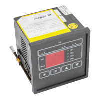
1.2 Identification plate:.........................................................................................................................5
1.3 Connecting the controller: .............................................................................................................6
1.3.1 Auxiliary power: ..........................................................................................................................6
1.3.2 Terminal connection diagram:....................................................................................................6
1.4 Mechanical Data:...........................................................................................................................6
2. TECHNICAL DATA, INPUTS:.................................................................................7
2.1 Analog inputs:................................................................................................................................7
2.1.1 Technical Data, inputs:...............................................................................................................7
2.1.2 Error-handling at input:...............................................................................................................8
2.2 Digital inputs:.................................................................................................................................8
3. CONTROL RESPONSE: ........................................................................................8
3.1 Controller function: ........................................................................................................................8
3.1.1 Two-point controller:...................................................................................................................9
3.1.2 Continuous-action controller:......................................................................................................9
3.1.3 Three-point response: ................................................................................................................9
3.2 Actuator function: ..........................................................................................................................9
4. OUTPUTS:............................................................................................................10
4.1 Potential-free relay contacts, make contact: ...............................................................................10
4.2 Logic output (optional):................................................................................................................10
4.3 Analog output: .............................................................................................................................10
4.3.1 Technical data, analog output: .................................................................................................10
4.4 Output responses in cases of error:............................................................................................11
5. DISPLAY:..............................................................................................................11
5.1 Upper 7-segment display ............................................................................................................11
5.2 Lower 7-segment display.............................................................................................................12
5.3 LED's:..........................................................................................................................................12
6. EXPLANATIONS OF SYMBOLS:.........................................................................12