gpelectric.com | [page 25]
TROUBLESHOOTING PROBLEMS
How to tell:
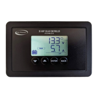
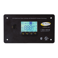
1. The State of Charge (SOC) screen is close to 100% and the Sun and Battery icon are present with an arrow between.
2. With the solar array in sunlight, check the voltage at the controller solar array terminals with a voltmeter.
3. If there is no reading at the controller solar array terminals, the problem is somewhere in the wiring from the solar array to the
controller.
Remedy:
Check all connections from the controller to the array including checking for correct wire polarity. Check that all connections are clean,
tight, and secure. Continue with the solutions below for additional help on low current readings.
Current Reading: Less than expected
Time of Day: Daytime, clear sunny skies
Possible Causes:
1. Current is being limited below 1 Amp as per normal operation.
2. Incorrect series/parallel conguration and/or wiring connections and/or wire gauge.
3. Dirty or shaded module or lack of sun.
4. Blown diode in solar module when two or more modules are connected in parallel.
5. The battery is full
How to tell:
1. Battery State of Charge screen is close to 100% and the Sun and Battery icon are present with an arrow in between.
2. Check that the modules and batteries are congured correctly. Check all wiring connections.
3. Modules look dirty, overhead object is shading modules or it is an overcast day in which a shadow cannot be cast.
Avoid any shading no matter how small. An object as small as a broomstick held across the solar module may cause the
power output to be reduced. Overcast days may also cut the power output of the module
4. Disconnect one or both array wires from the controller. Take a voltage reading between the positive and negative array wire. A
single 12 volt module should have an open circuit voltage between 17 and 22 volts. If you have more than one solar module, you
will need to conduct this test between the positive and negative terminals of each module junction box with either the positive
or the negative wires disconnected from the terminal.
Remedy:
1.
Reconnect in correct conguration. Tighten all connections. Check wire gauge and length of wire run. Refer to Suggested Minimum
Wire Gauge in Section 5.
2. Clean modules, clear obstruction or wait for conditions to clear.
3. If the open circuit voltage of a non-connected 12 volt module is lower than the manufacturer’s specications, the module may be
faulty. Check for blown diodes in the solar module junction box, which may be shorting the power output of module.
Note
 Loading...