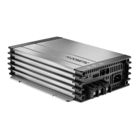
Connecting the device MCA1215 – MCA2440
24
The pins for the ESB socket (starter battery connection) are assigned as follows:
8.5 Setting the DIP switches
You can adjust the device using the DIP switch.
S1 is used to set the voltage at which the device switches over from the I phase (bulk)
to the U0 phase (absorption) (also see chapter “Battery charging function” on
page 17). S3 must be set to “OFF”.
S2 is used to set the retention voltage. S3 must be set to “OFF”.
When a battery sensor is connected, the output voltages is adapted to the
temperature for these two functions:
• MCA 12xx: –20 mV/°C
• MCA 24xx: –40 mV/°C
S3 activates the power mode when either S1 or S2, or both, are set to “Off”. In power
mode, the short circuit, overvoltage and overheating protection are controlled by
the internal sensor.
When S1, S2 and S3 are set to “On”, then the function control by external devices is
activated. Among others the type of battery and the charging voltage are set using
the external device in this mode.
S4 regulates the fan function. When S4 is set to “On”, then the fan is switched to
sleep mode (noise-reduced mode). When S4 is set to “Off”, then the fan is not
regulated.
Pin in
fig. 9, page 6
Allocation
+VCC
–GND
MCA1215-2440--IO-16s.book Seite 24 Freitag, 11. November 2016 9:15 21
 Loading...