26
EN
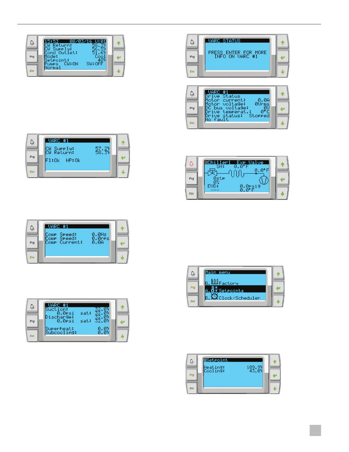
Operation VARC Chiller Controls
The screens following the main screen contain
information for each stage.
1. The first screen displays the CW Supply and CW
Return temperatures, flow switch status (Fl) and high
pressure status.
2. The next screen displays compressor speed and
information to indicate if the system is in a safety
count down. Once this time has elapsed and other
time delays have been met, the VARC starts up.
3. The next screen displays the suction pressure, the
discharge pressure, the superheat value, and the sub-
cooling value being calculated by the system.
4. The following screens display the drive status. To
access these screens, press Enter:
5. The final screen displays an image of the refrigerant
circuit and showing the valve position.
6.4.2 Adjusting Setpoints
1. Press the Program button. See “LCD Buttons” on
page 5.
2. Go to Setpoints, then enter the user password
(1234).
3. Press Enter once to update the Heating setpoint,
by pressing the Scroll Up or Scroll Down buttons to
change the value. Press Enter again to change the
cooling setpoint.