29
EN
VARC Chiller Controls Operation
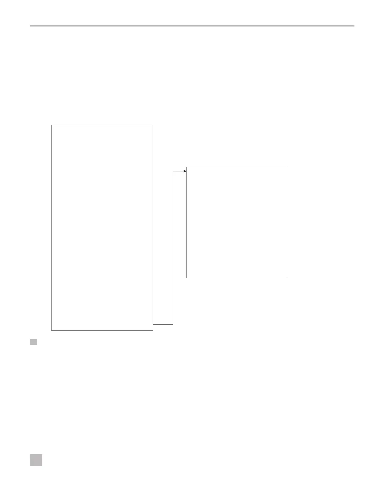
6.4.7 LCD Screen Menu Maps
The following diagrams show the menu options for each
screen available through the LCD displays.
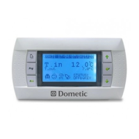
The Main screen is displayed at powerup. It displays the
essential system information.
I
An asterisk (*) indicates an option that is available
only when activated in the factory settings.
Main Status Screen
CW Supply Temp ##.#°F
Mode Off/Cool/Heat/ El Ht*
CW Return temp ##.#°F
CW Supply temp ##.#°F
Cond. Outlet temp ##.#°F
Mode Off/Cool/Heat/El Ht*
Pumps
CW On/Off
SW On/Off
Chiller Status Normal/Econo
Maint Mode Active
Stage # Auto/Disabled
Varc #1
CW supply temp ##.#°F
CW return temp ##.#°F
Flow status Ok/Alm/Off
High pressure status Ok/Alm/Off
Electric Heat* Ok/Alm/Off
Ok/Alm/Off
EH FL*
Compressor speed #.# Hz
Compressor
speed #.# rps
Compressor Current #.# A
Suction
Temperature ##.#°F
Pressure ##.# psi
Saturation Temp. ##.#°F
Discharge
Temperature ##.#°F
Pressure ##.# psi
Saturation Temp. ##.#°F
Super heat temp ##.#°F
Subcooling temp ##.#°F
VARC #* (if multistage)
Varc #1 information
Compressor Capacity Regulator
Required Capacity %
Actual Capacity %
Actual Speed rps
Drive Status
Motor Current #.# A
Motor Voltage # Vrms
DC Bus Voltage ### V
Drive Temperature ## °F
Drive Status Stopped/Running
Fault
Flow Diagram
Super Heat ## °F
Compressor ## °F
EEV Open % ## %
EEV Open Stps ### stp
EEV ### psi
23 Main Screen