34
EN
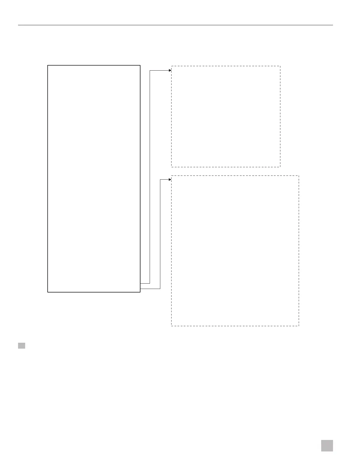
Operation VARC Chiller Controls
In the following diagram, the dotted boxes indicate a breakout of the additional information that is contained below that
menu category.
Temperature Limits
Low Suction Pressure
Cool Set Point ##.# bar
Heat Set Point ##.# bar
Inverter
Retrys #/## m
Set Disable ## s
Status #/## m
CW Pump Shutdown
Cool Setpoint ##.# °F
Heat Setpoint ##.# °F
Varc Type None/Varc48/
60/72/96
Compressor Scroll to select
Refrigerant R410A
Power type Based on Inverter
Power set Based on Inverter
Set Defaults Yes/No
Control Temp CCW supply/
CCW return
No. of stages #
Electric Heat (EH) Yes/No
Power Cycle Retain Mode/Off
Logo Select appropriate
Background Select appropriate
Flow Switch Yes/No
High Pressure Switch Yes/No
Low Pressure Switch Yes/No
EH Flow Switch* Yes/No
Load Shedding Yes/No
S
W Temp Inlet Yes/No
SW Pump settings
Control By demand/
By unit on
Off Delay ## s
Pump Current Yes/No
Current Select 10/30/50/75 A
CW Pump settings
Flow Prove Delay ## s
Off Delay ## s
Pump Current Yes/No
Current Select 10/30/50/75 A
Reversing valve
RV delay time ## s
RV toggle time ## s
RV delay ON time ## s
Electric Heat
Stg Up delay ## s
Stg Down delay ## s
Compressor
Econo mode SW Yes/No
Minimum On ## s
Minimum Off ## s
Min Time between Starts ## s
Load Up Time ## s
Frost Protection
Condenser Setpoint ##.#°F
Condenser Band ##.#°F
Compressor Speed ##.# rps
Envelope Zone (Envelope Status)
Control
Direct/Reverse/Both P/PID/P+I
K ##.#
Minimum ####
Maximum ####
DBd ##.#
28 Program/Factory/Factory Settings