37
EN
VARC Chiller Controls Operation
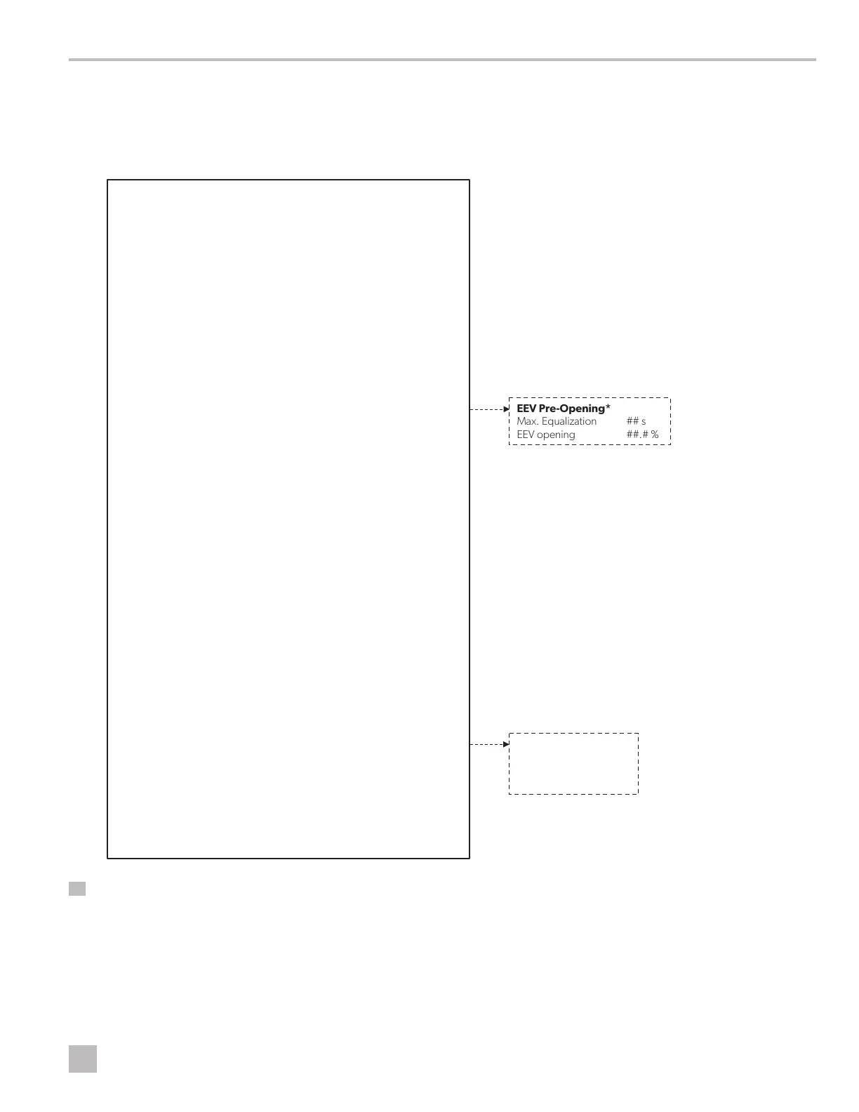
In the following diagram, the dotted boxes indicate a breakout of the additional information that is contained below that
menu category.
I
An asterisk (*) indicates an option that is available only when activated in the factory settings.
Output frequency min #.# Hz
Output frequency max #.# Hz
Skip frequency set #(1-3) #.# Hz
Skip frequency band #(1-3) #.# Hz
Switching frequency # kHz
Switching frequency derating Disabled/Enabled
Speed derating mode ##
Stop mode Ramp/Coast
Reverse Speed Disabled/Enabled
Flying Start Disabled/Enabled
Relay Configuration Select
PTC Alarm Disabled/Enabled
PTC Alarm delay ## s
Compressor Regulator
Start -up pressure differential contr
ol
Max pressure diff. admitted #.# bar
Equalization mode Equalztn valve/EEV Pre-Opening
Start -up failure control
Pressure diff. min. variation #.# bar
Control period ## s
Restart delay ## s
Max Retry # #
Speed Management
Start -up forced speed ##.# rps
Max speed ##.# rps
Min speed ##.# rps
Deceleration rate #.# rps/s
Acceleration rate #.# rps/s
Switch -off rate #.# rps/s
Envelope Control
Speed reduction rate #.# rps/s
Min speed admitted #
.# rps
Out of env. Alarm timeout ## s
Low press. diff. alarm timeout ## s
Discharge Gas Control High Discharge Temp.
Limit ##.# °C
Alarm ##.# °C
Speed Control due to Discharge Gas
Action Distance ##.# °C
Action Pause ## s
Comp. Speed Reduction #.# %
EEV Regulation
Mode Select from EEV Mode List
Discharge Temp Probe Comp Time ##.# s
Discharge Super Heat Temperature
Setpoint ##.# °C ##.# °C
Offset ##.# °C ##.# °C
Hystere sis ##.# °
C ##.# °C
Envelope Control - Low ratio management
By EEV closing Yes/No
By compressor speed Yes/No
Max. Equalization ## s
Suction Superheat
Discharge Temperature
Discharge Superheat
31 Program/Factory/Configuration/Power + n1 /Regulation