PSS5000/CONF/804473/40 33 of 54
PSS 5000 – Hardware Configuration Guide
Selecting the CPU Board and Interface Modules
Hardware configurations
and interface
connectivity
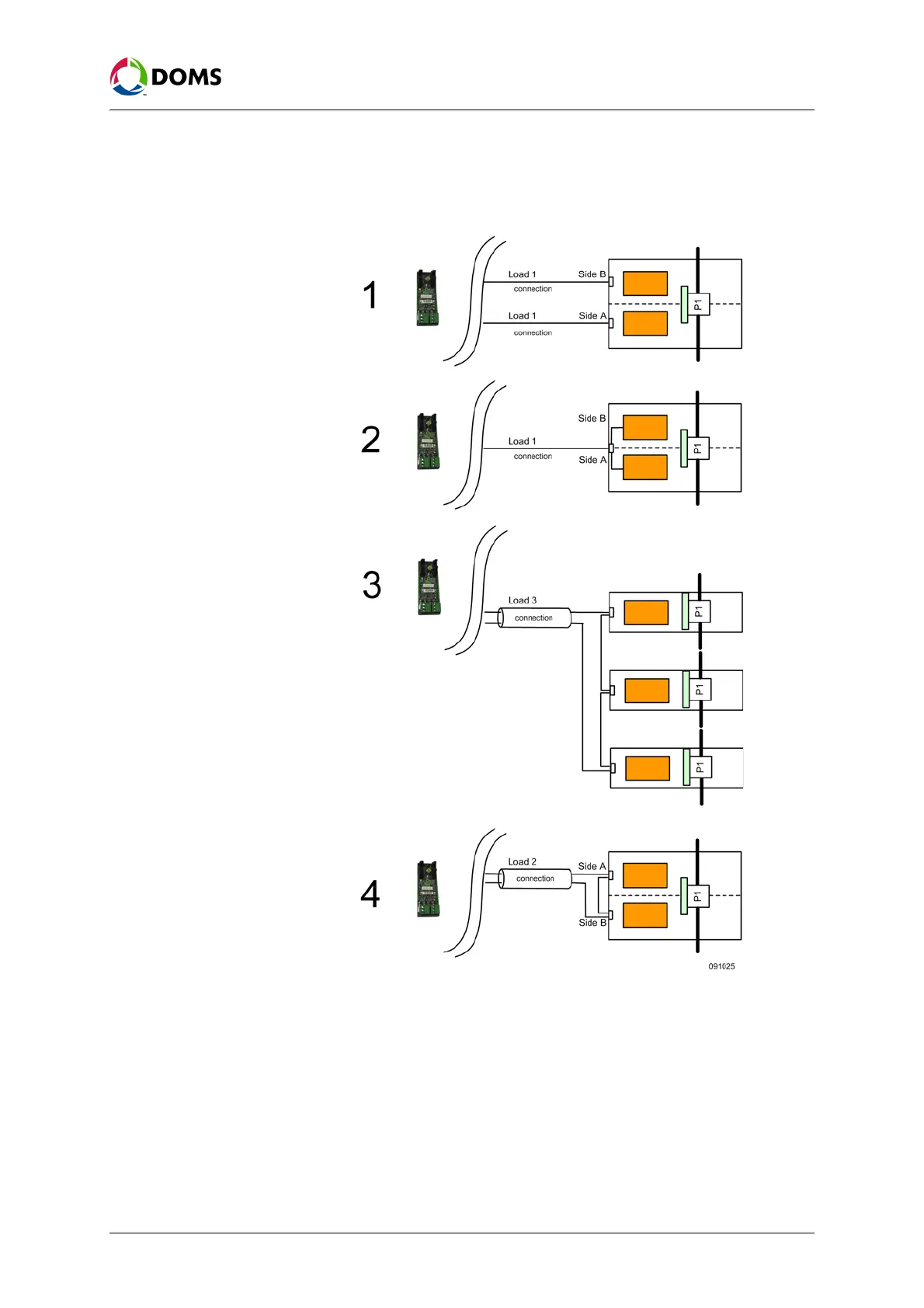
Multi-point devices, such as multi-point fuel dispensers, may have their hard-
ware configured in one of several different ways. Depending on how they are
configured they load the connection between the HIM and device differently.
This is illustrated below using dispensers:
Example 1 represents a dual-sided dispenser, where each dispenser is a device
and each device requires a connection to the HIM. In this situation, the load on
each HIM connection is 1 device.
Example 2 represents a dual-sided dispenser that uses a single HIM connec-
tion. Although this device contains 2 dispensers, the hardware configuration
means that the load on the single HIM connection is 1device.
Example 3 represents 3 single-sided dispensers where the current loop inter-
face is looped together in a daisy-chain configuration. In this configuration,
the load on the HIM connection is 3 devices.

 Loading...

