25
Note: For further details about the Front Panel
Editor, see the section entitled ‘Front Panel
Editor’ elsewhere in this manual.
Icon
Details
Appears when the engine is at rest and the
unit is in Stop/Reset Mode
Appears when the engine is at rest and the
unit in Manual Mode
Appears when the engine is at rest and the
unit is Test Mode
Appears when a timer is active, for example
cranking time, crank rest etc.
Front Panel Editor (FPE) / Auto Run Icon
When running in Auto Mode and on the Home
page, an icon is displayed in the FPE /Auto Run section
to indicate the source of the auto start signal.
/
Icon
Auto Run Reason
Appears when a remote start input is active
Appears when a low battery run is active
Mains failure
Appears when a scheduled run is active
Mode Icon
An icon is displayed in the Mode Icon section to indicate
the mode the controller is currently in.
Appears when the engine is at rest and the
unit is in Auto Mode
Appears when the engine is running, and all
timers have expired, either on or off load.
The animation speed is reduced when
running in idle mode.
Appears when the unit is in the front panel
editor.
Appears when a USB connection is made to
the controller.
Appears if either the configuration file or
engine file becomes corrupted.
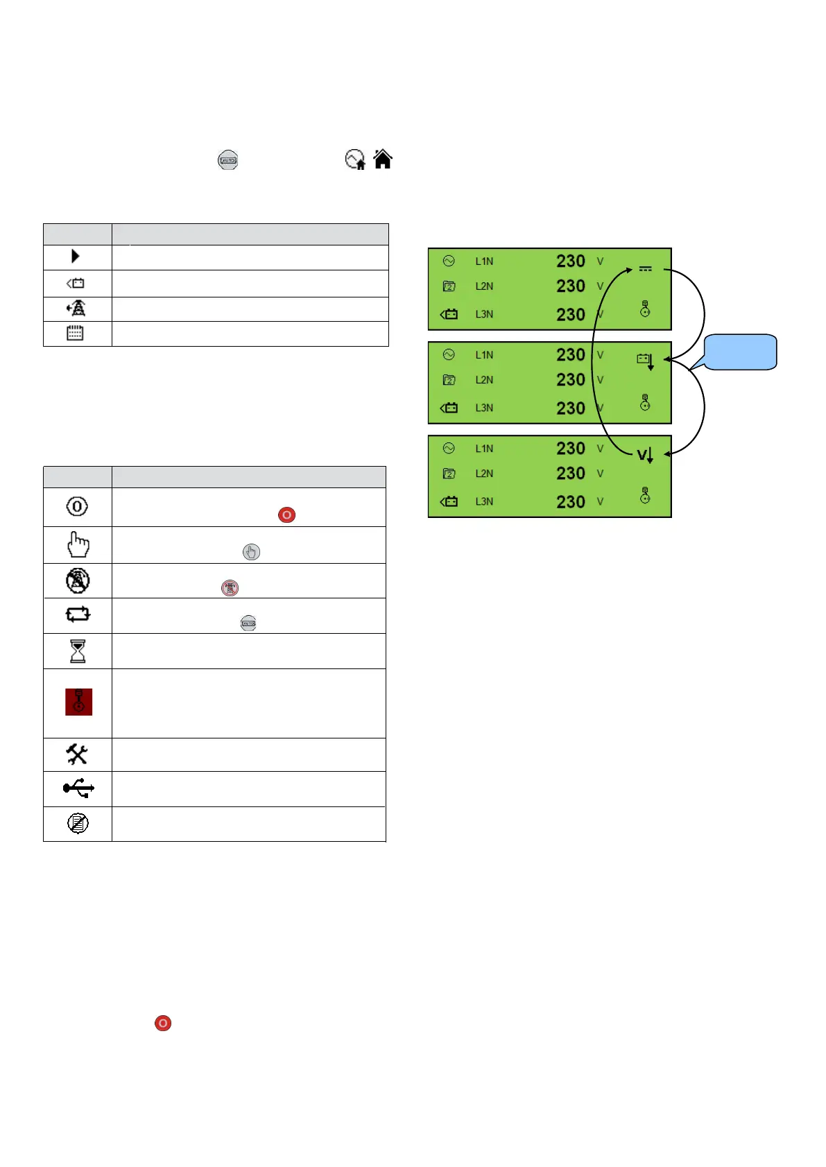
Alarm Icons (Protections)
An icon is displayed in the Alarm Icon section to indicate
the alarm that is current active on the controller.
In the event of a warning alarm, the LCD only displays the
Alarm Icon. In the event of an electrical trip or shutdown
alarm, the module displays the Alarm Icon and the
Stop/Reset Mode button LED begins to flash.
If multiple alarms are active at the same time, the Alarm
Icon automatically cycles through all the appropriate icons
to indicate each alarm which is active.
Example
If the DSE controller was sensing a charge alternator
failure alarm, delay over current alarm and a AC under
voltage alarm at the same time, it would cycle through all
of the icons to show this.
procedure