24
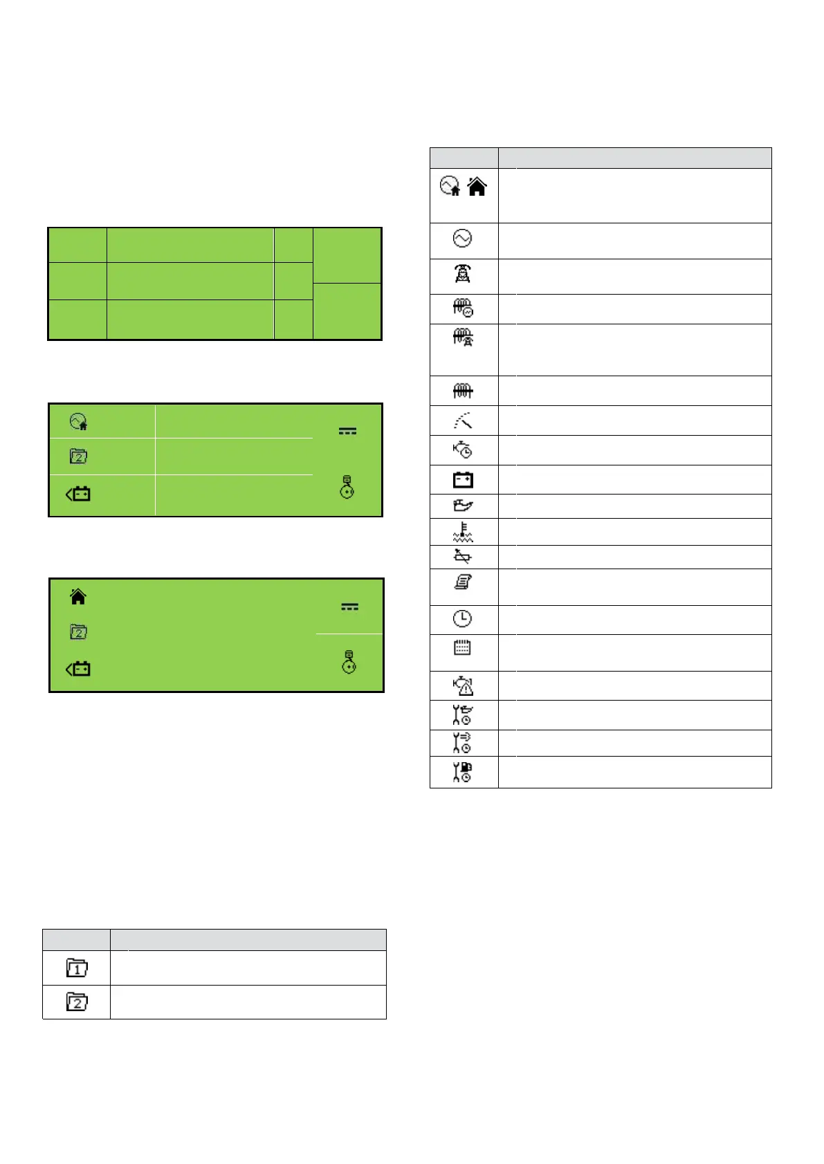
Example of DSE6010 MKII Home Page Display
MODULE DISPLAY
The module’s display contains the following sections:
Note: Depending upon the module’s configuration,
some display screens may be disabled. For
further details of module configuration, refer
to DSE Publication: 057-223 DSE60xx MKII
Configuration Software Manual.
Inst.
Icon
Instrumentation Unit
Alarm
Icon
Active
Config
Instrumentation Unit
Mode
Icon
Auto
Instrumentation Unit
L1N
V
L2N
V
L3N
230
V
Example of DSE6020 MKII Home Page Display
V
L1N
V
V
L2N
V
230 V
L3N
230 V
Backlight
The LCD backlight is on if the unit has sufficient voltage
while the unit is turned on, unless the unit is cranking for
which the backlight is turned off.
Instrumentation Icons
When viewing instrumentation pages, an icon is
displayed in the Inst. Icon section to indicate what section
is currently being displayed.
Generator current instrumentation screen
Load power instrumentation screen
Engine speed instrumentation screen
Hours run instrumentation screen
Battery voltage instrumentation screen
Oil pressure instrumentation screen
Coolant temperature instrumentation screen
Flexible sensor instrumentation screen
Current time held in the unit
ECU diagnostic trouble codes
Oil Filter maintenance timers
Air Filter maintenance timers
Fuel Filter maintenance timers
Icon
Details
The default home page which displays
generator voltage and mains voltage
(DSE6020 MKII only)
Generator voltage and frequency instrumen-
tation screen
Mains voltage and frequency instrumenta-
tion screen (DSE6020 MKII only)
Mains current instrumentation screen
(DSE6020 MKII only when CT in load
location)
Appears when the event log is being
displayed
The current value of the scheduler run time
and duration
Active Configuration
An icon is displayed in the Active Config section to indicate
the active configuration within the currently
selected within the controller.
Icon
Details
Appears when the main configuration is
selected.
Appears when the alternative configuration
is selected.