1.
2.
1
2
3
5 mm
5. Installing the drive unit
Secure the workspace against trespassing. Dropped
parts or tools may result in injuries.
The described procedure is only an example.
A different procedure might be preferable due to structural
or local conditions, available tools or other circumstances.
Requirements
• A 230 V/50-60 Hz connection with a fuse protection of
16 A must be available at the place of installation.
• The door panel must be in a sound mechanical
condition and smooth-running.
Standard tightening torques
M 5
......... 5 Nm
M 6
...... 9.5 Nm
M 8
....... 23 Nm
M 10
..... 46 Nm
M 12
..... 79 Nm
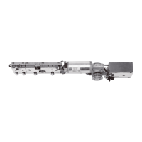
Required tools
2.5 mm
6 mm
2.5 mm
i
nsulated
6
mm
5 mm 13 mm
1/2/3
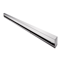
5.1 Removing the drive unit from the mounting plate
1. Loosen the 8 fastening screws.
2. Unplug the 230 V connector.
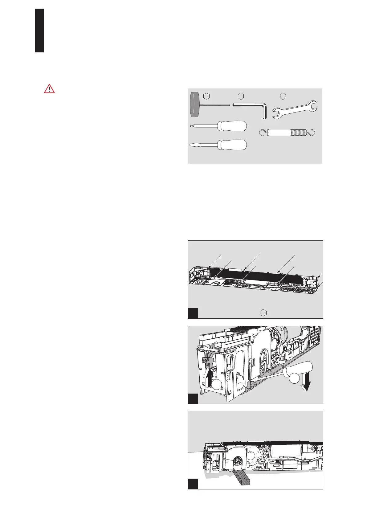
3. Disconnect the drive unit from the mounting plate.
Use a screwdriver as a lever between the drive unit and
the base plate.
4. Place a piece of wood or similar underneath the drive
unit so that the connecting part cannot come loose.
ED 100, ED 250
—
18

 Loading...