7.4 Performing a teach-in run
The teach-in run must be carried out while the motor
is cold. The door panel may not be moved manually
and stopped during the teach-in run. The control unit
would otherwise not be able to correctly determine the
parameters.
The safety sensors and activators are shut off during
the teach-in run so that they do not interfere with the
teach-in process.
The smoke detector and the shutdown drive function
are active.
1. Secure the movement range of the door panels.
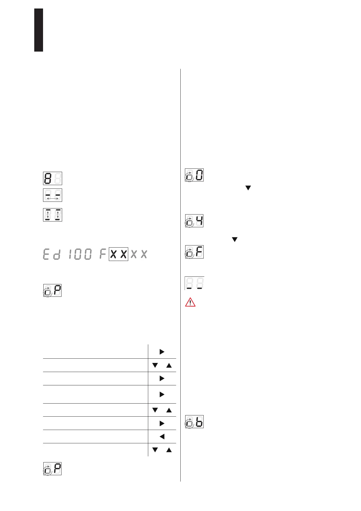
2. Close the door and turn the program switch to the OFF
position.
A spinning “o“ and “O“ indicate that a teach-in
run is required.
3. Press the pushbutton for 3 seconds.
► The door performs various movements and the display
shows a sequence of characters.
Do not stop the movements of the door panel.
The door is in the 70° position and waiting for the
opening width to be set.
4. Push the door to the desired open position and press
the pushbutton .
In case the spring force is too low, the display will
show the small spinning “o“ and “F“.
5. In this case, increase the spring force and restart the
teach-in run.
The door is now operational.
Due to system tolerances, the actual forces on the door
panel have to be measured after the teach-in run and
adjusted, if necessary, in order to comply with the local
standards and regulations.
7.5 Commissioning of a 2-panel system
1. Commssion the active panel.
2. Switch the program switch to PERMANENT OPEN after
the teach-in run.
3. Commission the inactive door panel.
Additional parameterization
• On the active panel:
Set parameter >dL< (door type) to “1“.
Set parameter >Ad< (caster angle) to the set value.
• On the inactive panel:
Set parameter >dL< to “2“.
7.6 Zero point search after mains reset
During the zero point search, the display will show
the small spinning “o“ and “b“.
7.7 Commissioning with integrated smoke detector
cf. mounting instruction ED Cover Basic RM,
ED Cover VARIO RM.
7. Commissioning
(also after a reset with factory setting (Fact-Setup))
7.1 Requirements
• The drive unit is completely installed and correctly
connected to the door panel.
• The parts delivered separately such as the program
switch and activator (microwave detector, night/bank
key switch) are installed and connected.
• The motor is cold.
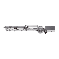
7.2 Commissioning the drive unit
1. Turn on the drive unit using the mains switch.
► The display shows a sequence of characters that
indicate the current processing status.
The system is being tested.
2 segments in the center moving back and forth
indicate that the control unit is waiting for internal
signals (maximum 1 second).
2 underlines moving up and down indicate the
mounting position can be entered. In case of an
incorrect input, the characters on the display are
upside down.
2. Press the lower pushbutton
(possible only during the initial commissioning).
The device identification will “run“ through the
display. ED 100 or ED 250 and the firmware
version (indicated by XX XX).
A small, spinning “o“ and “P“ indicate that a
further parameterization is required (only during
the initial commissioning or after a reset with
factory setting).
3. Set the following parameters: type of mounting (AS),
lintel depth (rd) and door width (Tb).
For the meaning and the value ranges of the
parameters, please refer to the table on page 34.
7.3 Changing the parameters
1. Press the pushbotton for 3 seconds in
order to call up the parameter menu.
2. Press the pushbuttons in order to select
the desired parameter.
or
3. Press the pushbutton in order to display
the parameter value.
4. Press the pushbutton in order to select
the value for the change.
=> The value flashes.
5. Press the pushbuttons in order to set the
desired value.
or
6. Press the pushbutton in order to save the
changed value.
7. Press the pushbutton in order to return to
the parameter menu.
8. Press the pushbuttons in order to select
the next parameter.
or
After leaving the parameterization mode, the
display will show a small, spinning “o“ and “P“.
ED 100, ED 250
—
31

 Loading...