97 98 99 30 31 32 34 33 3335
1
36
1
4
4a
3
BA
1
57 57a
142
3
141
3
1
15
17
3
111
13 3
43 3646362
1G
3
18k
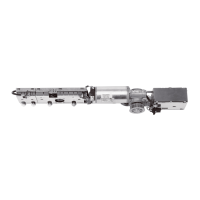
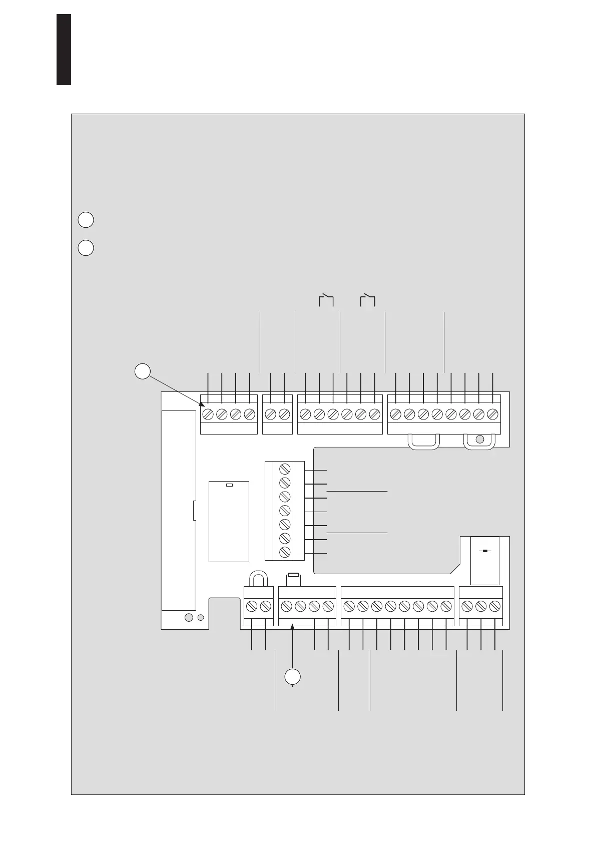
6. Connecting the accessories
1 Connect the connecting cables to the connector and insert the connector into the connection board.
• Maximum 1.5 A total load on the terminals 1, 1G and 3.
• Cable length maximum 30 m for J-Y(ST)Y 0.8 mm
6.1 Terminal assignment
The terminal is included in the scope
of delivery of the Upgrade Card DCW.
The terminal is included in the scope
of delivery of the Upgrade Card Fire
Protection.
If the Upgrade Card Fire Protection is
installed, you must connect either an
RM-ED or the load resistor 18 k.
0 V
B
A
8 – 24 V DC/AC + 5 %
+ 24 V
+ 24 V
Signal input
0 V
+ 24 V
COM
Locking relay
max. 1 A/48 V DC/AC
NO
NC
0 V
Locking response
0 V
+ 24 V
Signal input
0 V
0 V
+ 24 V
0 V
Signal input
0 V
Partial open
Permanent open
Exit only
Automatic
Off
NC
NO
Max. 1 A/48 V DC/AC COM
0 V
Signal input
Test output
+ 24 V
0 V
Signal input
Test output
+ 24 V
0 V
Night/bank
Shutdown
drive function
Smoke
detector
Night/bank
Program
switch
Status
relay
Pulse
external
Pulse
internal
Safety sensor
hinge side
Safety sensor
opposite hinge side
DCW
1
1
2
2
Connection depends on the
smoke detector
Open
closed
ED 100, ED 250
—
29

 Loading...