8. Installing Upgrade Cards
8.1 Requirements:
• The drive unit is completely installed.
• The teach-in run has been successfully completed.
• The mains voltage is turned on.
• The program switch is in the OFF position.
• The information display indicates an
inactive state.
8.2 Use in 2-panel systems
Full Energy: The Upgrade Card Full Energy can be
installed on one or both drive units.
Fire Protection: The Upgrade Card Fire Protection must be
installed on both drive units.
Professional: The Upgrade Card Professional will be
installed only on the drive for the active
panel.
DCW: The Upgrade Card DCW will be installed
only on the drive to which DCW products are
connected.
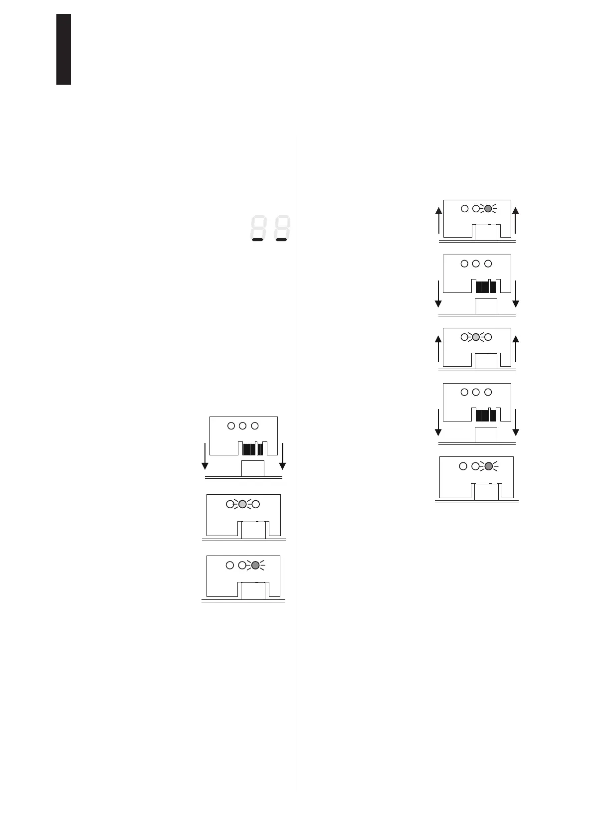
8.3 Installing the first Upgrade Card
1. Insert the Upgrade Card into
the slot
(see page 4 position 9).
► The yellow LED flashes once
during the insertion.
► The data are transmitted.
The communication between
the modules is indicated by
a slow flashing of the green
LED.
► The corresponding function is now enabled and can be
activated (see page 39, Parameter F1 – F8).
► The system is now operational.
8.4 Installing additional Upgrade Cards
You can install additional Upgrade Cards.
The first installed Upgrade Card assumes the function of the
container module. All installed functions can be used as long
as the container module is installed in the drive unit.
1. Remove the container
module.
2. Insert the next Upgrade Card.
► The function will be copied
into the drive unit and
the Upgrade Card will be
devalued.
3. Remove the Upgrade Card as
soon as the yellow LED is on.
4. Attach the container module.
► The control unit identifies
the container module and will
save the new function in it.
► The slow flashing of the green
LED indicates a successful
operation; the function can
be activated (see page 39,
parameter F1 – F8).
During the installation, also observe the following items:
• If the container module is removed, the previously
enabled functions will be deactivated after some time.
• For a new installation of the Upgrade Cards, it is
necessary to carry out an extended factory setting.
• In case the control unit is replaced, the container
module will be taken from the old control unit and
attached to the new one. The new control unit
synchronizes with the container module and all
functions will be available again.
• The Upgrade Card will be rejected if an already
enabled Upgrade Card is attached. This is indicated
by a fast flashing of the yellow LED. The module is not
devalued then.
• If the container module of an external control unit is
inserted, the container module will be rejected. This
is indicated by a fast flashing of the yellow and the
green LED. The module can be synchronized only with
a control unit.
ED 100, ED 250
—
32

 Loading...