3.2.4 Wind load control
The drive units ED 100 and ED 250 are especially suited for
external doors that are exposed to changing wind loads
or internal doors separating rooms in which pressure
differences might occur. In automatic mode, the wind load
control monitors the actual speed and will compensate for it
if the speed deviates from the set value. In combination with
the Upgrade Card Full Energy the drive unit can provide up
to 150 N at the main closing edge, which can then be used
to compensate for environmental influences.
The closing process during the last 5° can be additionally
supported by the electronic latching speed.
The door can be passed through manually. We recommend
the Push & Go function.
3.3 Low energy product
The ED 100/250 can be adjusted so that the requirements
of a low energy application (low energy drive unit) are in
accordance with the EN 16005 or DIN 18650, ANSI 156.19
and BS 7036-4. During the commissioning, the drive
parameters must be adjusted according to the specifications
of the respective standard.
The required safety of the system will be achieved with the
following characteristics:
• Reduced dynamic door panel forces/contact forces
• Low speeds
• Reduced static door panel forces/contact forces
• Force limitation
Due to system tolerances, the actual forces on the door
panel have to be measured after the teach-in run and
adjusted, if necessary, in order to comply with the local
standards and regulations.
Additional safety sensors to safeguard the rotational
movement are not required but optional if this becomes
necessary due to a risk assessment to be carried out
individually.
The safeguarding of the secondary closing edge must be
considered separately.
3.4 Control elements
The drive units ED 100 and ED 250 are electromechanical
drives. The interaction between motor gear unit and control
unit makes the automatic opening and closing possible
in the first place. The control unit must know certain
parameters of the door in order to achieve the ideal behavior.
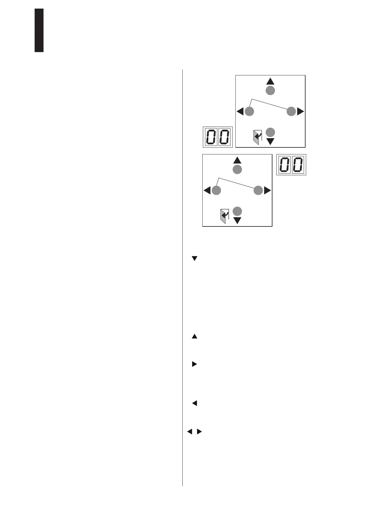
The control unit is equipped with a user interface featuring 4
pushbuttons and a 2 digit display. This allows you to make
all settings specified in the parameter list.
During the commissioning, the key functions and the display
are configured in such a way that - independent of the
installation direction of the pushbuttons - always the same
functions and the numbers and digits are shown correctly.
The legend of the pushbuttons can be removed and turned.
< 3s Quit
> 3s Reset
< 3s
> 3s
LEARN
> 8s
Fact-Setup
> 3s
PRG
DIN L
< 3s Quit
> 3s Reset
< 3s
> 3s
LEARN
> 8s
Fact-Setup
> 3s
PRG
DIN R
By pressing the pushbuttons, you can execute the following
functions:
Lower pushbutton
• Setting of the installation direction following a mains
reset
• Browsing in parameters and error messages
• Reducing the parameter value
• Opening pulse
• Teach-in run
• Reset with factory setting (Fact-Setup)
Upper pushbutton
• Browsing in parameters and error messages
• Increasing the parameter value
Right pushbutton
• Open parameter menu
• Change selected parameter
• Save changed value
Left pushbutton
• Cancel parameter change
• Exit parameter menu
Left and right pushbutton simultanuously
• Error acknowledgement
• Reset
ED 100, ED 250
—
5
 Loading...