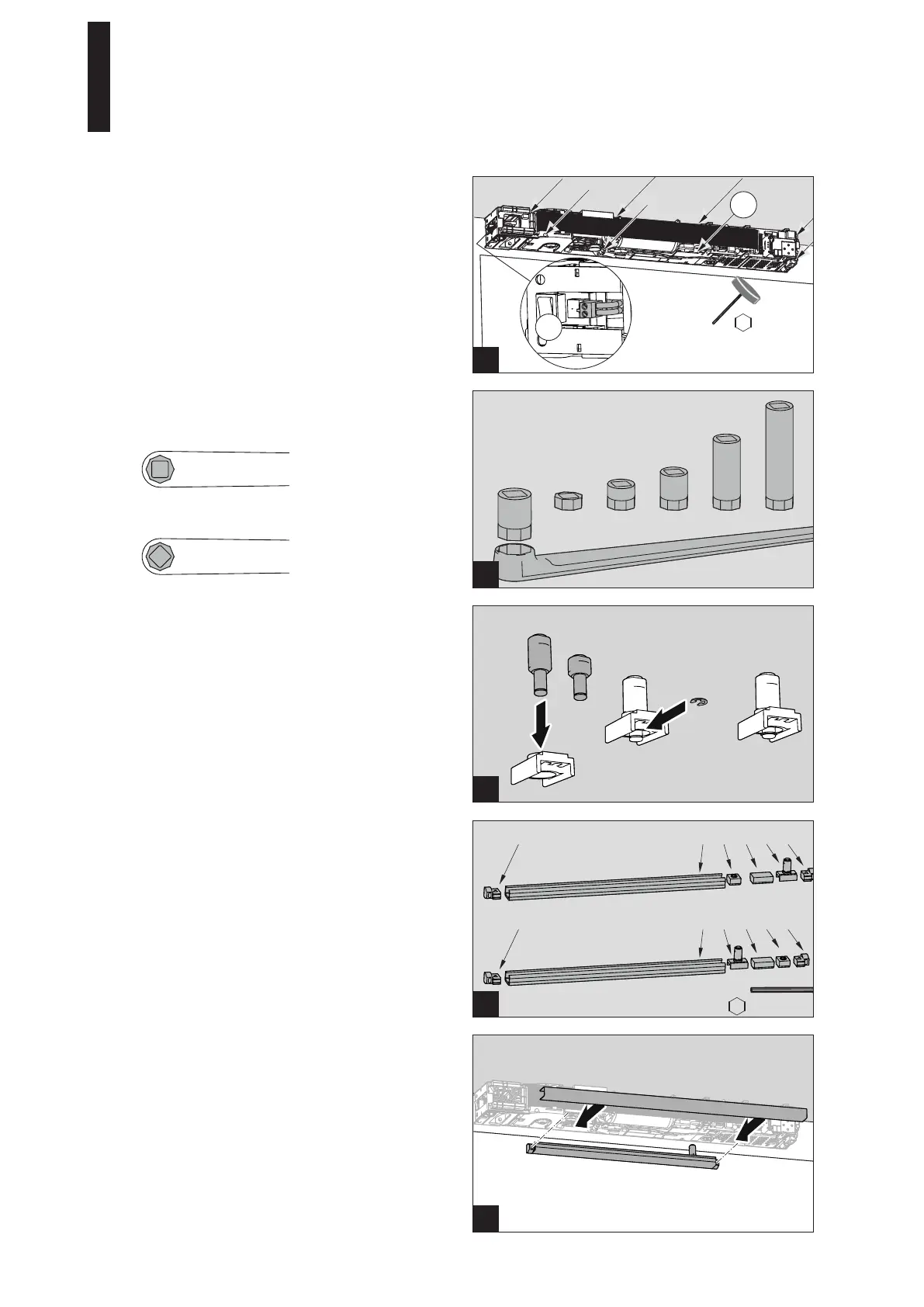
9 mm 20 mm 30 mm 60 mm 90 mm
1.
2.
3
1 2 3 4 55
1 4 3 2 55
1
2
3
25 mm
12.5 mm
2.5 mm
1
5 mm
DIN L
DIN R
4. Tighten the 8 screws firmly.
5. Plug in the mains connection plug.
5.6 Installing the Slide Channel
1. Insert the pivot pin (12.5 or 25 mm) into the slide shoe
and fix it with the lock washer.
The short pin is used for doors without a rebate.
2. Guide the individual parts into the slide channel as
shown in the figure and screw down the fixing pieces.
1 Slide channel
2 End stop
3 Buffer
4 Slide shoe
5 Fixing piece
3. Screw the slide channel down into the prepared holes
with 2 screws.
Use dowels and screws adapted to the substructure for
fixing.
4. Place the cover on the slide channel.
5.5 Driving the Axle Extension into the Lever
1. Drive the axle extension into the lever.
Installation position when installing on the hinge side.
Installation position when installing on the opposite
hinge side; the square must be rotated by 45°.
ED 100, ED 250
—
18 DORMA