EasyManuals Logo

Dorma ED800 J User Manual

Dorma ED800 J
28 pages
To Next Page IconTo Next Page
To Previous Page IconTo Previous Page
Page #18 background imageLoading...
Page #18 background image
ED800-18 08102710 05/07
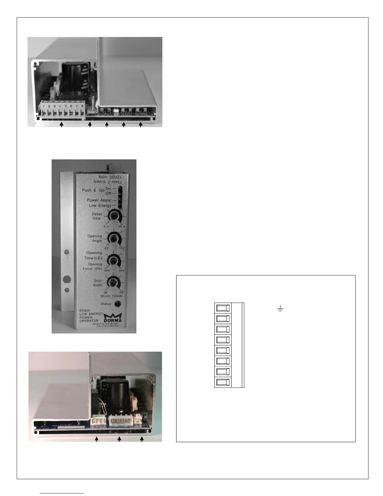
ED800 Controller Module Diagram
External Connector (See below)
Encoder Connection
Transformer/Motor Connection
Battery (Factory use only)
Hold Open Switch Connection
Closing Obstacle Switch (Off/On)
Mount Style Switch (Push/Pull)
Latch Delay Switch (Off/On)
External Connector
NOTE: Terminal can be removed from control
module to simplify installation of wires. The
maximum recommended wire size is 18 AWG.
7
8
6
VESTIBULE
5
BUSY SWING (SAFETY)
2
+12VDC
4
OPEN TRIGGER
31
GROUND
NC
C
NO

Questions and Answers:

Question and Answer IconNeed help?

Do you have a question about the Dorma ED800 J and is the answer not in the manual?

Dorma ED800 J Specifications

Power IconPower
voltage120 Volts AC
operating frequency50/60 Hz
current2 Amp
Fuse Specifications IconFuse Specifications
fuse current3 Amp
fuse typetype AGC
fuse size1/4" x 1 1/4"
Auxiliary Power Output IconAuxiliary Power Output
auxiliary voltage range10 to 25 Volts DC
auxiliary current500mA
relay contact rating48 VAC/DC @ 1 Amp Max.
Radio Frequency Receiver IconRadio Frequency Receiver
frequency300 MHz std. or 310 MHz jumper selectable
supply voltage12 - 30 Volts AC/DC
power consumption rest16mA
Wall Switch Specifications IconWall Switch Specifications
switch typeSPDT
switch rating15 Amp @ 125 or 250 Volts AC
battery type9 Volt NEDA 1604

Related product manuals