ED800-6
ED 800J - TOP JAMB INSTALLATION TEMPLATE & MOUNTING INSTRUCTIONS
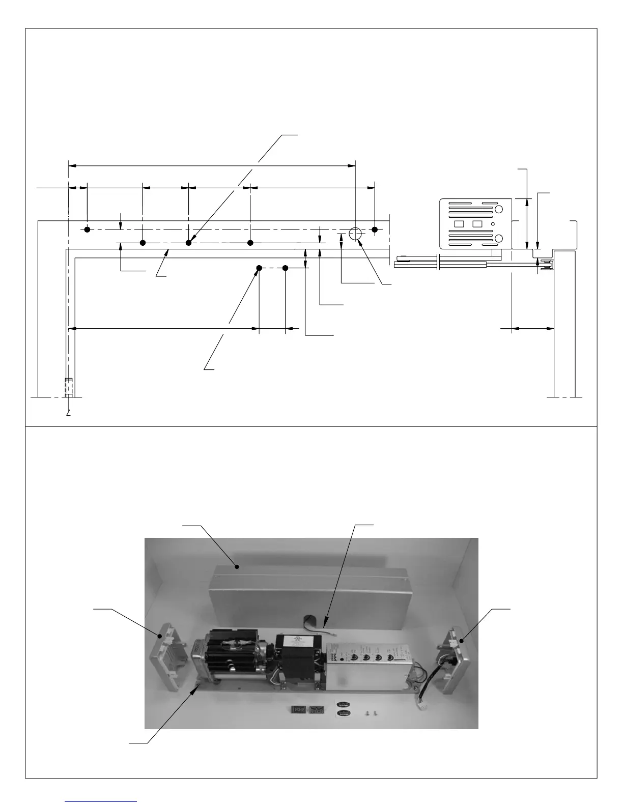
Prepare door and frame according to template.
Remove two (2) cover screws and cover. Disconnect cover ground wire at base plate. Loosen,
but do not remove end cap screws and slide end caps off.
Note:
Re-install end caps, cover ground wire and cover after installation is complete. Push-in emblems
or logo decals can be applied to hide cover screws if needed.
(224)
1-3/4
(44)
(44)
(11)
7/16
3. LEFT HAND DOOR SHOWN.
BOTTOM OF FRAME
REVEAL
NOTES:
C
OF 4-1/2" WIDE HINGE, 3/4" OFFSET PIVOT,
1. DO NOT SCALE DRAWING.
2. DIMENSIONS ARE IN INCHES/(MM).
5. SEE CATALOG FOR ARM NUMBER FOR NON STANDARD REVEALS.
FOR 1/4-20 MACHINE SCREWS USE No.7 (0.201") DRILL
FOR No. 14 WOOD SCREWS USE 5/32" DRILL
FIVE (5) HOLES IN FRAME FOR PLATE
FOR 1/4-20 MACHINE SCREWS USE No.7 (0.201") DRILL
FOR No.14 WOOD SCREWS USE 5/32" DRILL
FOR SEX NUTS USE 3/8" DRILL
TWO (2) HOLES IN DOOR FOR ARM SHOE
8-13/16
1-3/4
SEE
NOTE
# 5
2" TO 6" STD.
3-1/4
(83)
3-15/16
(110)
7/8" DIA. HOLE FOR
WIRE ACCESS
MINIMUM TO CEILING 4-1/4"
1-5/16
(33)
12-5/8
(321)
20-11/16
(525)
15/16
(24)
6. MAXIMUM OPENING ANGLE 115°.
4-3/8
(111)
7. DOORS AND FRAMES MUST BE PROPERLY REINFORCED.
1-3/32
(28)
8. IF STOP PROJECTION IS OVER 5/8"
USE ED800 x DROP INSTALLATION.
SEE NOTE
# 8
5/8" MAX.
INDIVIDUAL DOOR MANUFACTURER'S LISTINGS.
ALTERNATIVE METHOD IS IDENTIFIED IN THE
COMPOSITE TYPE FIRE DOORS, UNLESS AN
DOORS AND TO WOOD OR PLASTIC FACED
ATTACHMENT OF COMPONENTS TO UNREINFORCED
4. CAUTION: SEX NUTS ARE REQUIRED FOR
9. AUXILIARY STOP, (BY OTHERS) ARE REQUIRED AT 115° FOR
INSTALLATIONS WHERE DOOR CAN OPEN MORE THAN 115°.
ED800-1 Rev.08/04
08102710 05/07
COVER
END CAP END CAP
WITH
SWITCHES
GROUND WIRE FOR COVER
END CAP
SCREW
(LEFT HAND MOUNT SHOWN)