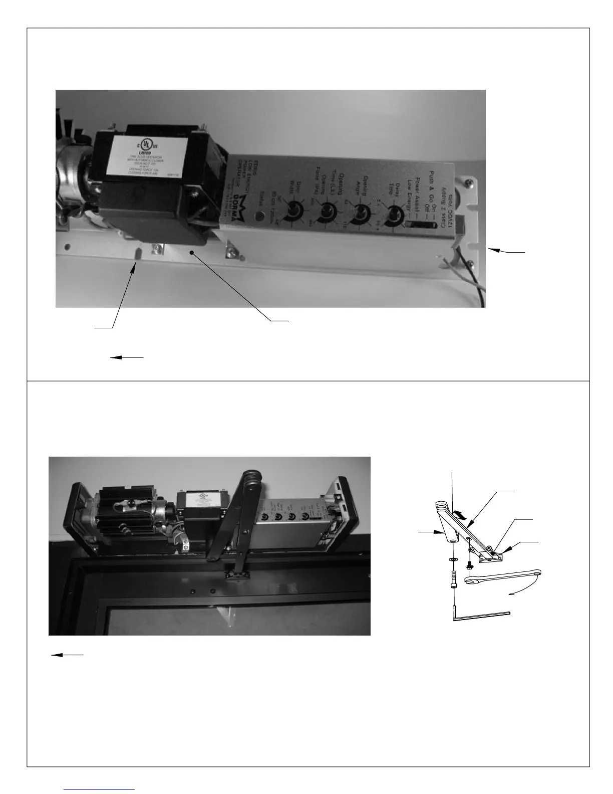
EasyManuals Logo

Dorma ED800 J User Manual

Dorma ED800 J
28 pages
To Next Page IconTo Next Page
To Previous Page IconTo Previous Page
Page #7 background imageLoading...
Page #7 background image
MAIN
ARM
6 mm HEX KEY
LOCK WASHER
PINION SCREW
ARM SHOE
CONNECTING
ROD
ARM
Orient arm as shown. Attach arm shoe to door. Place wrench on top pinion shaft and rotate pinion
slightly toward latch edge of door. Slide main arm over bottom pinion shaft. Fasten securely with
pinion screw and lock washer provided. Loosen screw in connecting arm so arm slides freely.
Adjust connecting arm length so rod and connecting arm are 90° to door. Re-tighten screw.
08102710 05/07ED800-7
Initially install screws for slots "A" as pictured, allowing 5/16" between the screw head and the frame.
Align the slots in the mounting plate with the screws. Slide the mounting plate over the screw and hold
the unit in place until the balance of the screws are installed. Tighten all screws securely.
MOUNTING
PLATE
SLOT "A"
SLOT "A"
HINGE SIDE OF DOOR
HINGE SIDE OF DOOR

Questions and Answers:

Question and Answer IconNeed help?

Do you have a question about the Dorma ED800 J and is the answer not in the manual?

Dorma ED800 J Specifications

Power IconPower
voltage120 Volts AC
operating frequency50/60 Hz
current2 Amp
Fuse Specifications IconFuse Specifications
fuse current3 Amp
fuse typetype AGC
fuse size1/4" x 1 1/4"
Auxiliary Power Output IconAuxiliary Power Output
auxiliary voltage range10 to 25 Volts DC
auxiliary current500mA
relay contact rating48 VAC/DC @ 1 Amp Max.
Radio Frequency Receiver IconRadio Frequency Receiver
frequency300 MHz std. or 310 MHz jumper selectable
supply voltage12 - 30 Volts AC/DC
power consumption rest16mA
Wall Switch Specifications IconWall Switch Specifications
switch typeSPDT
switch rating15 Amp @ 125 or 250 Volts AC
battery type9 Volt NEDA 1604

Related product manuals