20 79/RT/E7900/770/E-760/660 Series PK3678_T 04-18
(L)
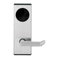
Override
Shaft
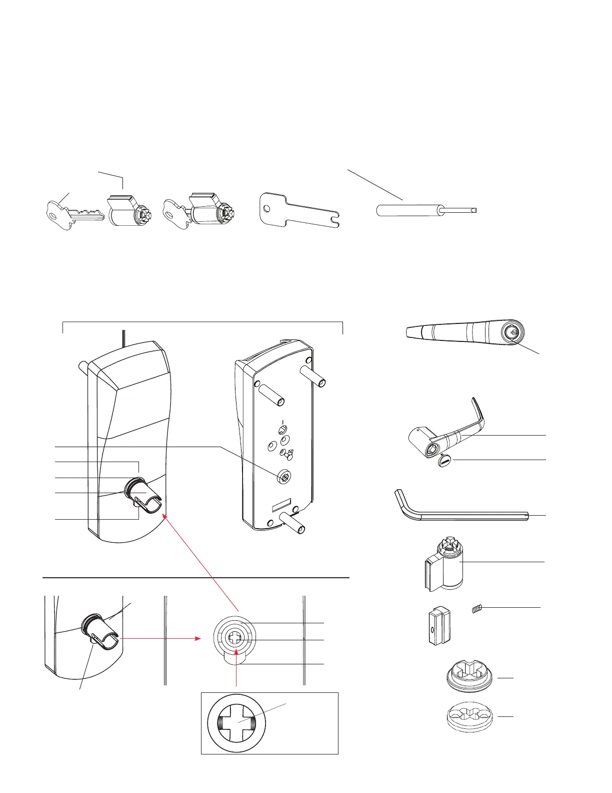
Parts and Tools List
NOTE: For the purposes of Section 9 use the naming convention listed below in Parts and Tools List and Diagram of lock.
Tools Required:
Cylinder (J, provided with lock) or equivalent ( T ) Small flat scewdriver (less that 1/8")
(A) Lock housing
(B) Inside drive hub
(C) Nylon washer
(D) Spring washer
(not for lever feel)
(E) Drive tube
(F) Lever catch
(G) Countersink
(H) Lever handle
(I) Cap
(J) Cylinder
(K) Cylinder plug
(K1) Set Screw
(M) Allen Key
(O1) Adapter
(O2) Adapter & Screw
(L) Override shaft
Diagram of lock:
Facing view of drive tube: (E)
BackFront
(A)
(H)
(I)
(E)
(B)
(D)
(F)
(M)
(J)
(O1)
(O2)
(K1)
(E)
(L)
(F)
(G)
(C)
(F)
(E)
(N)
9 Installation of Mechanical Override Models
 Loading...