17
1.1 Mortise Installation (Metal Extrusion)
1.
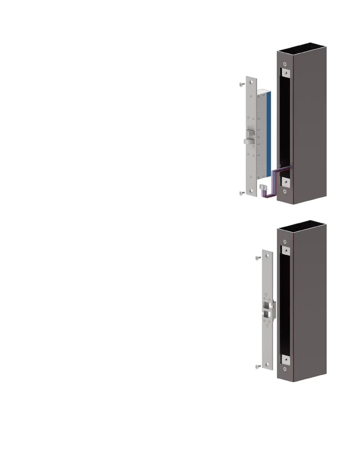
Referring to the product dimension drawings, a mortise is cut into the
door frame to fit the lock and a mortise is cut into the door leaf to fit
the strike. Metal doors and frames, being hollow, often only require a
single rectangle cut-out to accommodate the lock face plate or strike
plate. For these installations lock and strike can be installed flush using
fitting tabs (available separately).
It is crucial to ensure that the mortises in the door leaf and frame
are aligned vertically and horizontally when the door is closed as this
aligns the bolt pin to the strike opening and also the strike magnet to
the locks internal door position sensor.
Ensure that the final gap between the lock face plate and strike plate
once it is installed will be no more than 6mm
(¼ inch).
2.
Feed the wires out of the hollow chamber of the frame and a
connection can be made to the supplied wire loom which in turn plugs
into the lock.
Refer to the Wiring section of this document for detailed
instructions on wiring.
3.
Ensure the operating mode switch is positioned to the required state, Fail
Safe or Fail Secure.
Refer to the Operating Mode section of this document for detailed
instructions on wiring.
4.
The lock can be placed into the door frame cutout, ensuring that the wiring
integrity is maintained, and then secured in place with M5 machine screws
(included with fitting tabs). Please ensure the lock is the correct orientation
as to pull the door into the door jamb.
The strike is then placed into the door leaf cutout and then M5 machine
screws (included with fitting tabs) are used to secure it in place. Ensure the
strike is oriented so that the bolt hole aligns with the lock bolt.
 Loading...