18
1.1 Surface Mounting Installation (Solid Wood)
1.
Install two 10Gx1” self-tapping screws (included with housing) in the mounting
surface, as per the product dimension drawings they should be 220mm apart,
20mm from the surface edge.
2.
An 8mm hole should be drilled through the housing wall at the position chosen
by the installer for the wiring to enter. The wiring can be guided to the housing
through surface mount conduit, or through a hole in the mounting surface
material. Push a rubber grommet (included with housing) over the drilled hole
to protect the wires from any sharp edges.
3.
Position the keyhole cutouts of the housing over the screw heads and slide
into position flush with the surface edge, and then tighten screws in place to
secure the housing.
4.
Feed the wires through the 8mm hole in the housing and a connection can be
made to the supplied wire loom which in turn plugs into the lock.
Refer to the Wiring section of this document for detailed
instructions on wiring.
5.
Ensure the operating mode switch is positioned to the required state,
Fail Safe or Fail Secure.
Refer to the Operating Mode section of this document for detailed
instructions on wiring.
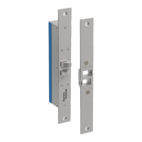
6.
The lock can be placed into the housing, ensuring that the wiring
integrity is maintained, and then secured in place with M5 machine
screws (included with housing). Please ensure the lock is the correct
orientation as to pull the door into the door jamb.
 Loading...