20
1.1 Wiring Guide
The SL30DBL is supplied with a 7-way wire loom that plugs directly into the lock. The wires are colour coded
as per table below, with the power and control wires being essential connections and the four monitor
connections being optional.
Wire Colour Meaning Description
RED
Power Supply
(12 - 24VDC)
Positive connection to DC power supply, “”
BLACK Negative connection to DC power supply, “”
BLUE Control Switched positive control input
VIOLET
Bolt Position
Monitor
Normally open contact (NO), closed when the bolt
pin is extended (optional)
VIOLET
WHITE
Door Position Monitor
Normally open contact (NO), closed when the
strike is aligned with the lock (optional)
WHITE
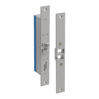
1.2 Fail Safe Connection
When in Fail Safe configuration, applying positive voltage to the control wire triggers the SL30DBL to lock
(active-high locking signal). In the event of a power cut, the SL30DBL will unlock.
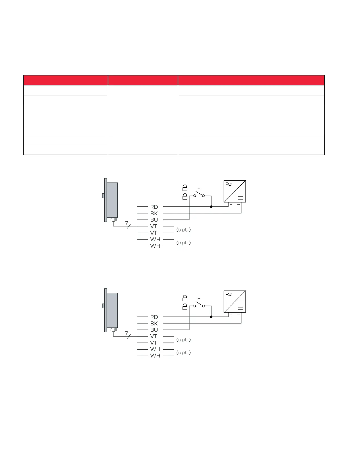
1.3 Fail Secure Connection
When in Fail Secure configuration, applying positive voltage to the control wire triggers the SL30DBL to unlock
(active-low locking signal). In the event of a power cut, the SL30DBL will remain locked.
 Loading...