Dräger PIR 3000 – Installation Instructions
Any use of the gas transmitter requires full understanding and strict observation of the Instructi-
ons for Use of the Dräger PIR 3000 (Order No. 9023812).
How to Install the Gas Transmitter
Only trained service personnel (e.g. Dräger Safety service personnel) may install the gas transmitter under observation of relevant regulati-
ons.
Mounting Location
The protecting effect of the gas transmitter depends on the selection of the mounting location. By taking the site's air flow conditions into
account, the best possible mounting location should be chosen as close as possible to where a decisively noticeable rise in gas concentration
can be expected in case of a leakage, i. e.
— as close as possible to the potential leakage place
— when monitoring gases and vapours which are lighter than air: above the potential leakage place
— when monitoring gases and vapours which are heavier than air: near to ground.
In addition, it must be assured that:
— the air circulation in the gas transmitter vicinity is not hindered
— the danger of mechanical damage is reduced as far as possible
— the gas transmitter is sufficiently accessible for maintenance purposes. Especially the configuration via magnetic pin requires a clearance
of approx. 20 cm around at least half of the sensor perimeter.
The gas transmitter can be mounted horizontally as well as vertically.
Electrical Installation
The entire wiring must correspond with applicable local regulations concerning the installation of electrical devices in potentially explosive
atmospheres. In case of doubt, the official responsible authorities are to be consulted prior to installation of the device. We recommend a
three-core, screened connection cable (mesh wire shield with a shielding factor of ≥80 %).
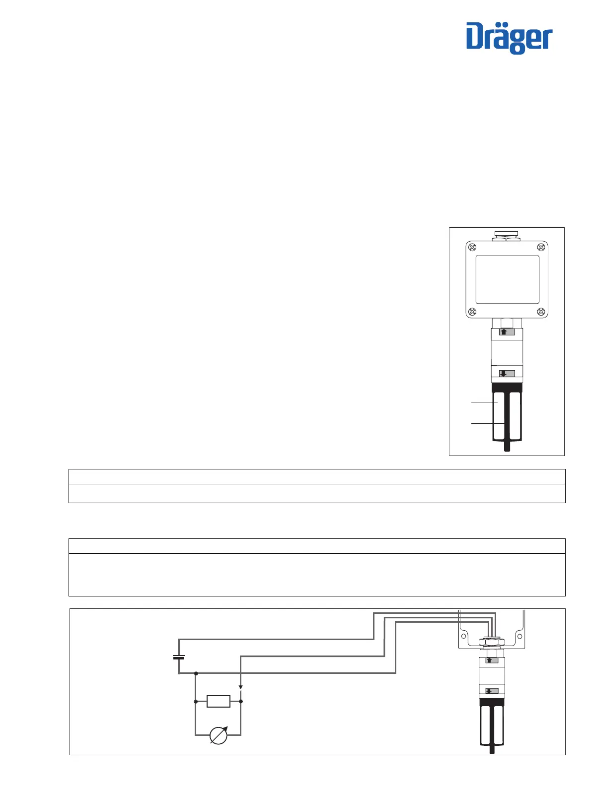
Connection Diagram:
Mechanical Installation
Terminal Box
The gas transmitter is designed to be directly attached to a terminal box. Approved connector boxes of the
following makes are available as gas transmitter accessories: Ex d (explosion proof, 3/4" NPT) and Ex e
(refer to the Instructions for Use).
The enclosed O-ring seal must be used for a connection using type of explosion protection Ex e, to
maintain the housing protection class. The M25 nut (torque of 15 Nm ±3 Nm) must be secured against
self-loosening a using thread locking adhesive, e.g. Loctite
®
.
Any unused cable entry openings at the terminal box must be closed using approved plugs.
Splash Guard and Calibration Adapter
We recommend using the supplied accessories - splash guard (1) and calibration adapter (2) - to increase
protection against water jets and contamination.
The splash guard is held by a fixture provided with screw-thread, which is also used as calibration adap-
ter.
The correct fit of the calibration adapter must be ensured. To correctly fit the calibration adapter, tighten it
by hand until the sealing line leaves a permanent mark in the splash guard.
NOTICE
If present: If the connector of the gas transmitter is not required, it must be removed prior to the electrical installation.
To do this, use a suitable tool to sever and isolate the cables directly before the connector.
NOTICE
Earth leakages on two phases can cause EMC problems. To avoid these problems, the cable screen may only be connected to earth poten-
tial on one side (either at the central unit or at the gas transmitter). In most cases we recommend connecting the cable screen to the PE ter-
minal of the terminal box instead of connecting it to the central device.
For applications in accordance with directive 2014/90/EU or the standard DNVGL-CG-0339, the gas transmitter or the gas detection system
may not be connected to a DC voltage supply network but rather to a suitable separate power supply unit (see Technical data).
0
S
00223813_02.eps
(1)
(2)
00123813_02_en.eps
+
0
S
red
brown
black
R
I
4 to20 mA
10 to 30 V DC
at gas transmitter
U

 Loading...


