11
Operational Characteristics
Operational Characteristics
The gas transmitter generates an output signal which is proportional to the
measured gas concentration. The factor of proportionality between displayed value
and the measured gas concentration is determined by the span calibration of the
gas transmitter (see "Manual Span Calibration of the Output Signal." on page 15).
The gas transmitter regularly runs self tests for numerous internal functions. As
soon as a divergence from normal operation is detected, the device will issue a
fault message.
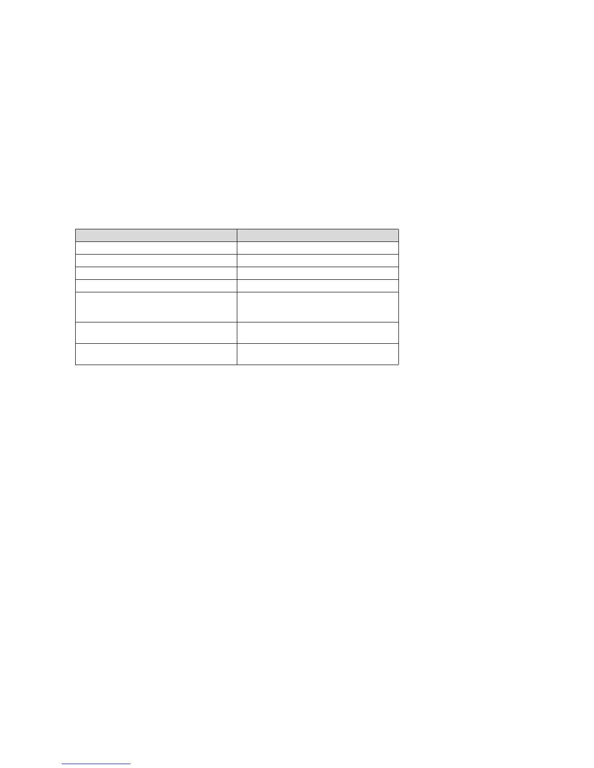
Output Signals of the Device:
Calibration
A functional check and - if necessary - a calibration must be carried out regularly for
gas warning systems (see page 20, Maintenance).
Zero gas and test gas are to be applied for functional check and calibration of the
infrared gas transmitter Dräger PIR 3000. To this end, the gas is applied either with
— the calibration adapter in connection with the splash guard (see page 5, part of
the scope of delivery) or
— the gas exposure / process adapter (see page 6 and order list) or
— the dirt deflector in connection with the splash guard (see order list).
The required gas flow rate for functional check and calibration is as follows:
— 0.5 to 1 L/min. for the calibration adapter with splash guard and the dirt deflector
with splash guard in closed rooms at wind speeds up to 5 m/s (3 Beaufort),
— 1 to 2 L/min. for the calibration adapter with splash guard and the dirt deflector
with splash guard at wind speeds up to 27 m/s (10 Beaufort),
— 0.5 to 3 L/min. for the gas exposure / process adapter.
Display of Output Signal
zero point 4 mA
full scale deflection 20 mA
under-range 3.8 mA to 4 mA
over-range 20.0 mA to 20.5 mA
span gas signal to indicate begin and
successful termination of gas transmitter
calibration via magnetic pin
3 mA
Fault and inlet signal (during self check
and running-in period)
1 mA
Warning (while increasing the Drift of the
zero point into the negative range)
2 mA