Installing the Gas Transmitter
8
Electrical Installation
The entire wiring must correspond with applicable local regulations concerning the installation of electrical devices in
potentially explosive atmospheres. In case of doubt, consult the responsible authorities before installing the device.
We recommend a three-core, screened connection cable (mesh wire shield with a shielding factor of ≥80 %).
The leads for the sensor are factory sealed.
If the corresponding connection is available:
Electrically connect the terminal box to earth.
For installation in conduit: cast conduit seals and allow to harden.
When installing a complete set (see "Order List" on page 27):
depending on the housing type of the terminal box there are the following permissible conductor cross sections:
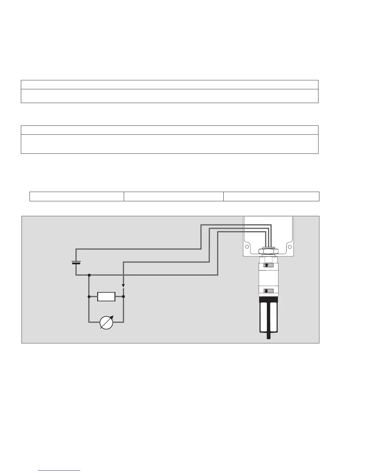
Connection Diagram:
Colour code of connecting terminals and/or leads at the gas transmitter:
NOTICE
If present: If the connector of the gas transmitter is not required, it must be removed prior to the electrical installation.
To do so, cut the cables with a suitable tool directly in front of the connector, strip the insulation, and attach suitable ferrules.
NOTICE
Earth leakages on two phases can cause EMC problems. To avoid these problems, the cable screen may only be connected
to earth potential on one side (either at the central unit or at the gas transmitter). In most cases, connecting the cable screen
to the PE terminal of the terminal box has proven to work better than connecting it to the central device..
Order No. 68 11 160: 1.0 to 2.5 mm
2
Order No. 68 11 270: 0.5 to 4.0 mm
2
Order No. 68 11 180: 0.2 to 4.0 mm
2
1 = black = – (common reference potential)
2 = brown = signal output 4 to 20 mA
3 = red = + (10 to 30 V DC)