Installing the Gas Transmitter
6
Installing the Gas Transmitter
Only trained service personnel (e.g. of Dräger) may install the gas transmitter
under observation of relevant regulations.
Installation and commissioning are described in the "Dräger PIR 3000 Installation
Instructions" which are supplied with the gas transmitter.
Mounting Location
The protecting effect of the gas transmitter depends on the selection of the
mounting location. By taking the site's air flow conditions into account, the best
possible mounting location should be chosen as close as possible to where a
decisively noticeable rise in gas concentration can be expected in case of a
leakage, i. e.
— as close as possible to the potential leakage place
— when monitoring gases and vapours which are lighter than air:
above the potential leakage place
— when monitoring gases and vapours which are heavier than air:
near to ground.
In addition, it must be assured that:
— the air circulation in the gas transmitter vicinity is not hindered
— the danger of mechanical damage is reduced as far as possible
— the gas transmitter is sufficiently accessible for maintenance purposes.
Especially the configuration via magnetic pin requires a clearance of approx.
20 cm around at least half of the sensor perimeter.
The gas transmitter can be mounted horizontally as well as vertically.
Mechanical Installation
When used according to BVS 05 ATEX E 143 X, please note:
The gas sensor type IDS 0001 (NPT) can be attached to casings with the type
of protection flameproof enclosure "d" that have a free volume of 2 litres and a
reference pressure that does not exceed 20 bar. The mechanical strength of the
attachment and the explosion and construction-related testing of the connection
thread must be carried out within the framework of the approval process of the
electrical equipment to which the sensor is attached.
The gas sensor type IDS 0011 (metric thread) is designed for attachment on a
casing with the type of protection increased safety "e". The mechanical strength
and the degree of protection IP 6X of the attachment must be ensured during
approval of the electrical equipment to which it is attached.
The junction boxes of the gas sensors IDS 00** must feature sufficient
mechanical stability to ensure that the vibrations transmitted to the sensor by the
casing are not amplified.
Terminal box
The gas transmitter is designed to be directly attached to a terminal box.
Approved connector boxes of the following makes are available as gas transmitter
accessories: Ex d (explosion proof, 3/4" NPT) and Ex e (increased safety, M25) -
(see "Order List" on page 27).
To maintain the housing protection class, the enclosed O-ring seal must be used
for an Ex e-type explosion protection connection.
Use a thread locking adhesive, e.g. Loctite
®
to prevent the M25 nut (torque of
15 Nm ±3 Nm) from self-loosening.
Use approved plugs to close any unused cable entry openings at the terminal
box.
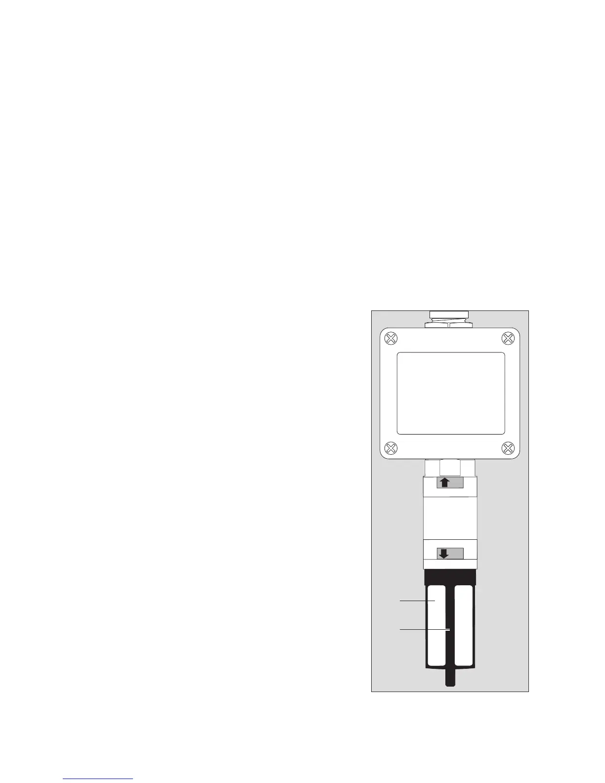
Splash Guard and Calibration Adapter
We recommend using the supplied accessories - splash guard (1) and calibration
adapter (2) - to increase protection against water jets and contamination.
0
S
00323812_02.eps
(1)
(2)