Client Drayton File Name 75 42 Dr ayt on LP 10R F & DIG IS TAT+2 RF 06 515 08 600 1 ISS C
Artworker -
Proof Stage
PRINT
Finished Size A5 148x210mm
Creative Director Mike Lane Artwork % 100%
Modification Date 21/08/15 2:56PM Bleed 3mm
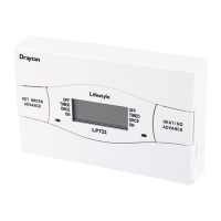
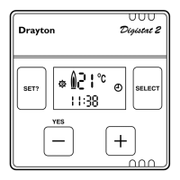
Installation Guide LP10RF & DIGISTAT+2RF
CLOCK?
Before fixing the DIGISTAT+2RF to the wall it is
recommended to first check the signal strength from that
location.
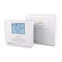
To do this, after initial start up, the colon, CH and antenna
symbols should be ashing on the LP10RF display.
1.
Press the set? button 4 times.
2.
Press the OK button once.
3.
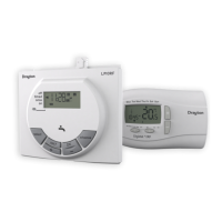
Press the set? button 4 times; Lrn and OFF should
be displayed.
4.
Press the + button so the display shows ON and a
ashing antenna symbol. The learn mode is now
ready to receive a signal from the transmitter
during the next two minutes.
5.
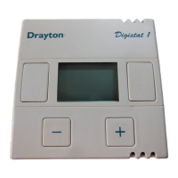
Take the Digistat+2RF unit and stand near the
boiler.
6.
Remove the battery cover and t the batteries.
7.
The symbols on the receiver will stop ashing and
the display will show ‘SSI, Antenna and ON’.
8.
Press ‘SET’ on the receiver and the display will
show ‘SSI and Antenna’.
9.
After a few seconds the display will show ‘- - -’.
Remove the batteries from the Digistat+2RF,
press and hold the ‘+’ button whilst retting the
batteries, keep the ‘+’ button held and after a few
seconds the display will show ‘rF’ which indicates
that the DIGISTAT+2RF is continuously sending a
signal to the LP10RF (receiver).
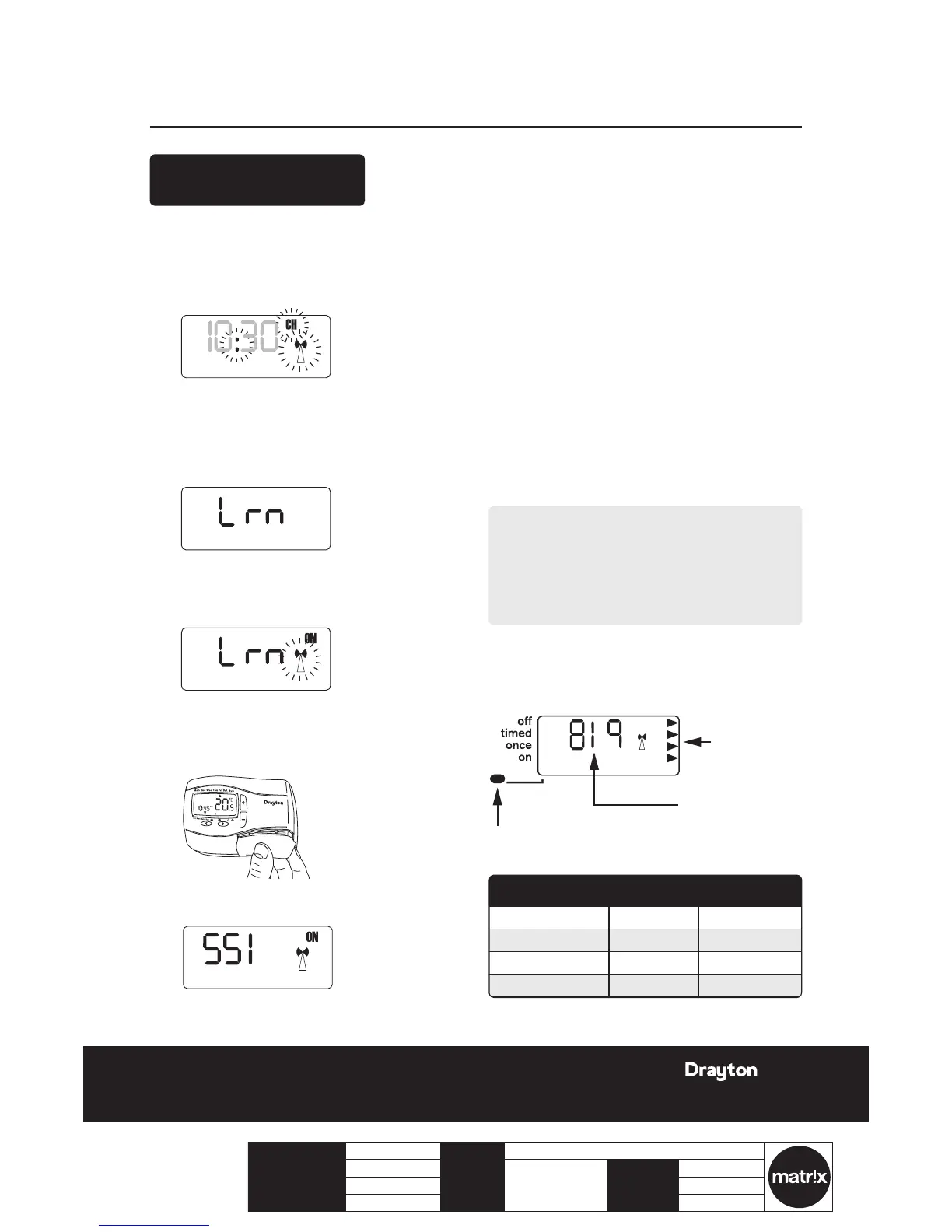
The receiver display will now show the ‘learnt’
transmitter code and the antenna’ as well as the
signal strength as indicated by the chevrons on the
right hand side of the display.
J
Place the transmitter in the desired nal position
and return to the boiler to check the receiver
display. The ideal transmitter position will result
in the receiver display showing 4 chevrons and the
LED will be green.
K
If the LED is red or no LED is showing and the
display indicates 1 or 2 chevrons, the transmitter
will need to be re-positioned until the LED
changes to amber or green and 3 or 4 chevrons are
indicated on the display.
NOTE:
If there is no LED and the display shows ‘- - -’, there
is no signal being received at all from the transmitter.
Transmission will resume once the transmitter is re-
positioned in a part of the house where an amber or
green LED and 3 or 4 chevrons are achieved.
L
Once you are happy that, when in the desired
location, the transmitter is sending a good signal
to the receiver i.e. amber or green and 3 or 4
chevrons, the transmitter can be xed to the wall.