15
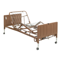
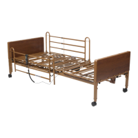
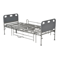
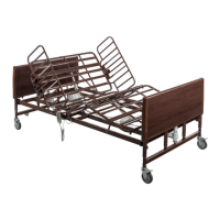
2. Connecting the Spring Sections: Full Electric; Semi Electric; Manual
A. Remove the Head Spring from carton and place on its side to your right with the center mounting latches to
your left.
B. Remove the Foot Spring from carton and place on its side to your left with the foot spring mounting latches
to your right.
C. The Head and Foot Springs should now be positioned upright on their sides at approximately a 90-degree
angle to on another.
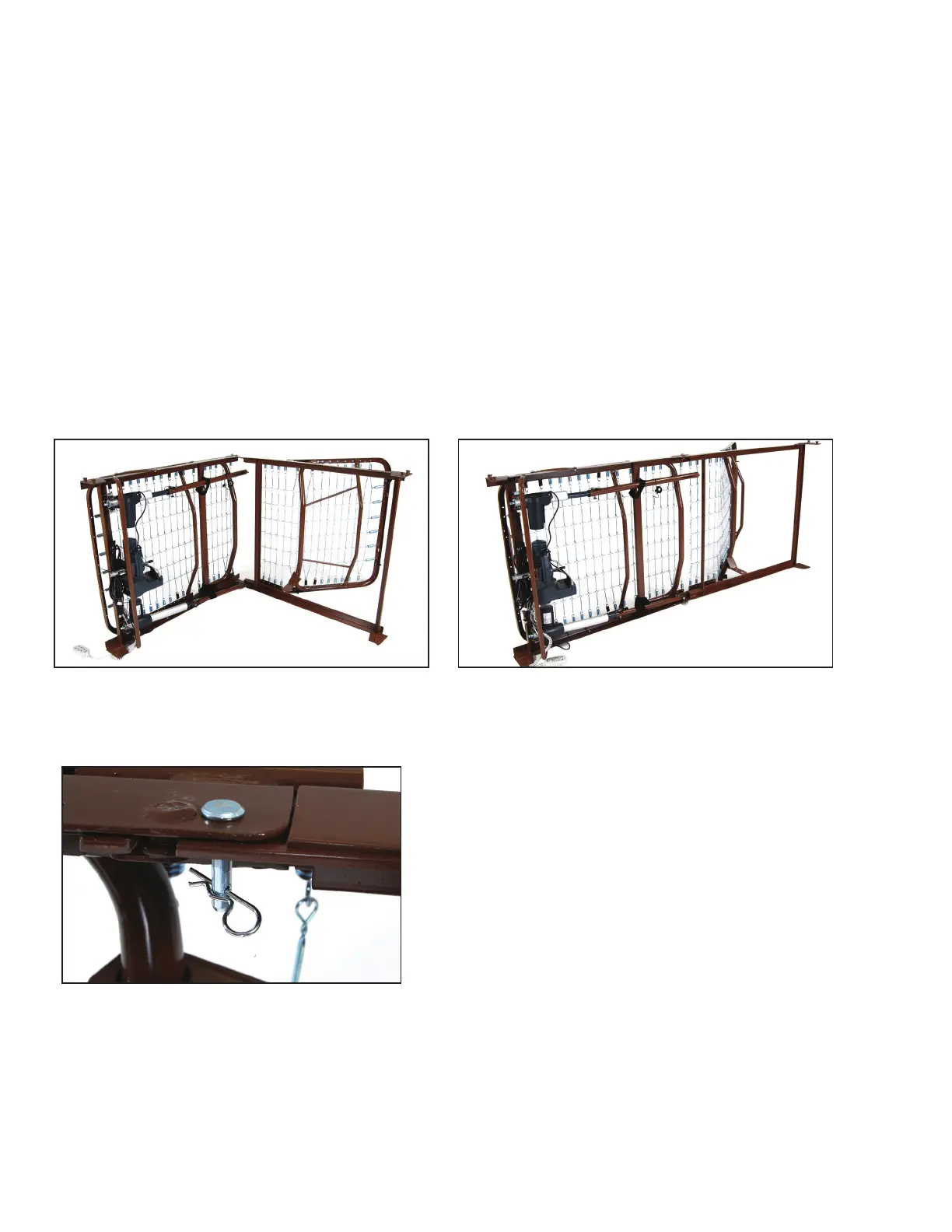
D. Connect the Head Spring to the Foot Spring by aligning the mounting latches and swinging both ends
away from each other so both springs are now hooked and aligned in a straight/horizontal position.
NOTE: It may be necessary to lift the Head and/or Foot Spring slightly to align and engage the mounting
latches to the mounting pins.
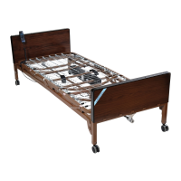
Note: 15005LP shown for illustrative purposes only for assembly
3. Optional: Insert lock pin through connected sleep surface and secure with spring clip.
ASSEMBLY
C D
B
A