17
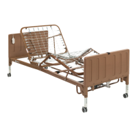
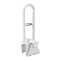
5. Install the casters by inserting the stem of the
caster into the leg receptacle. It is recommended
to install one locking caster and one non-locking
caster on each bed end. The locking casters
should be installed diagonally from each other.
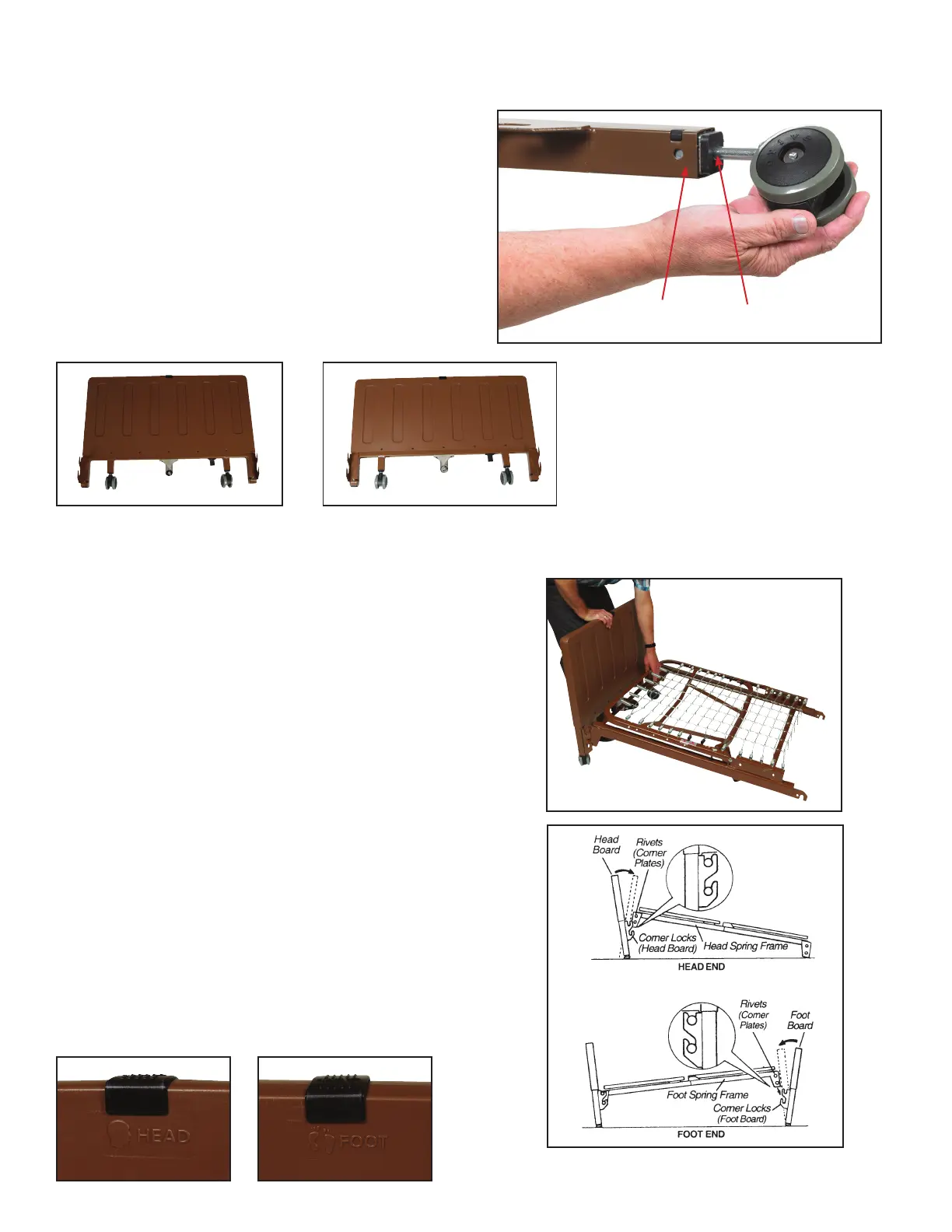
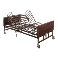
The 15005LP Low Height bed gives you the option of
installing the casters on the inboard non adjustable
legs or the outboard adjustable legs. To achieve
the full low height feature, install the casters on the
inboard non-adjustable legs.
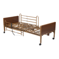
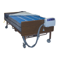
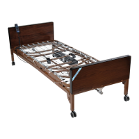
6. Install bed ends:
A. Carefully lower the bed frame at onto the oor.
Attach the Head and Foot Boards by tilting the Boards
toward your body and aligning mounting pins located
on the Spring Sections with the Hooks on the
Head/Foot Boards.
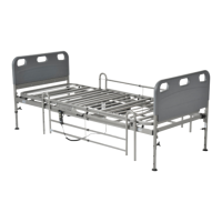
B. Stand the Head Board as close to the Head Spring as
possible.
C. With one hand, grasp the Head Spring Frame and
raise it until the frame connecting pins are at the
correct height to t into the Bed End Hooks.
D. Tilt the Head Board backward slightly and the pins
should slide into the hooks.
E. When the Head Board is returned to its full upright
position, the Head Board will lock into place.
F. Repeat the same procedure for the Foot End Section.
NOTE: The Head Board is taller than the Foot Board,
however, they are interchangeable with each other.
Head and foot boards are embossed on the top.
StemLeg Receptacle
ASSEMBLY