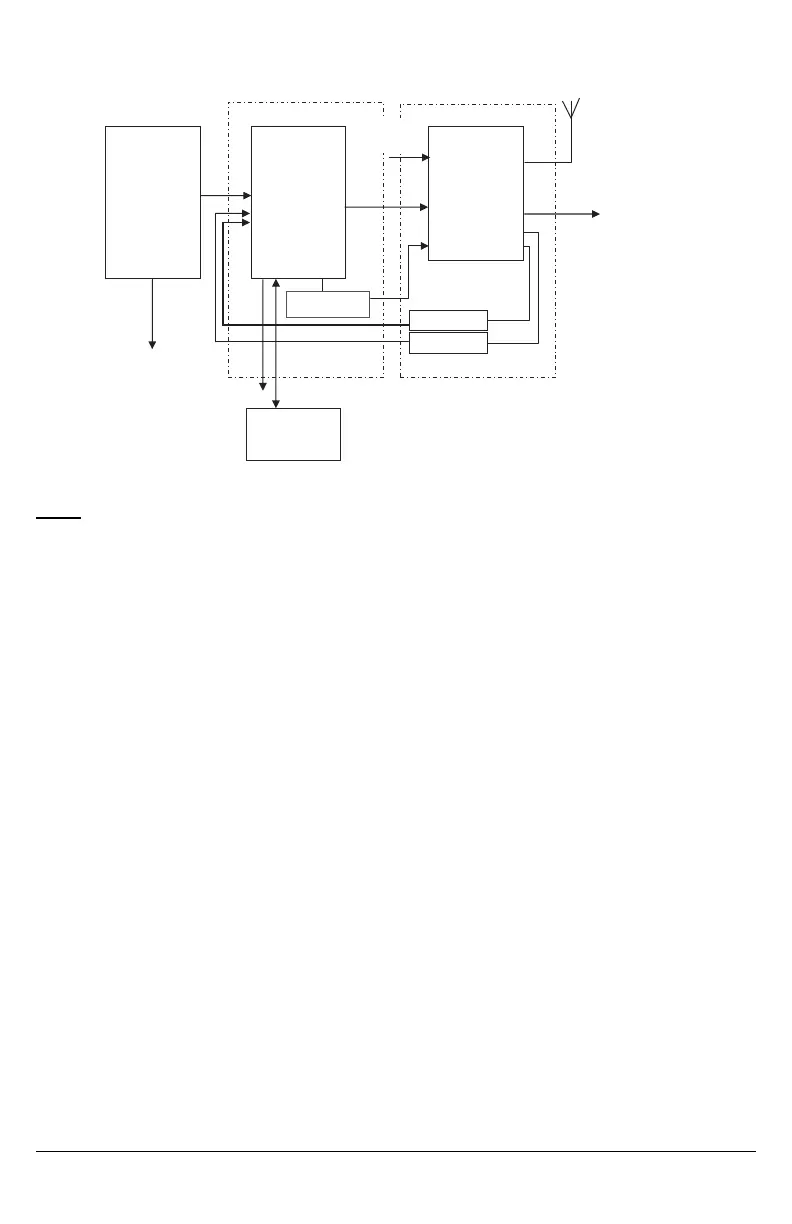
Figure 8: DSC Subscribers’ Unit Fire and 3G Cellular Transmitter Mounted Remotely
Alternate Wiring Diagram for DSC Subscribers’ Unit Fire and Cellular Transmitter Passive Communication System -
Using Phone Line Supervision Relay
Fire Alarm
Control Unit
Outputs
Fire
Supervisory
Trouble
DSC
Subscribers’
Unit Fire
Zone
Inputs
TIP
RING
PGM1
DSC Keypad
LCD4501
PK55XX
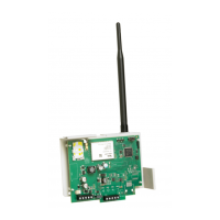
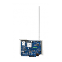
3G Cellular
Transmitter
3G4010
T1/R1
PGM1
TIP/RING
Zone
Input PGM4
AUX Power
12V/700mA
RM1C ULC
Relay
PC5003C
PC4050CR
cabinet
3G (HSPA)/2G (GPRS)
PSTN
AC Input
AC Input
PC4020
PC1864
PC1832
PC1616
RM1C ULC
Relay
GS4010 cabinet
RM1C ULC
Relay
PLEASE NOTE THAT EITHER RM1C ULC OR RM2 RELAYS CAN BE USED FOR ULC INSTALLATIONS
NOTES:
l Connect PGM output from 3G4010 (Phone Line Trouble) to a zone input on the subscriber unit for supervision of the
phone line voltage.
l When the 3G4010 is installed remotely from the DSC Control Panel, it is required to monitor the Phone Line Trouble con-
dition at the keypad by using an additional RM1C Relay.
22