The following wiring diagrams (Figures 6 to 8) are examples of ULC Listed Fire Monitoring Installation connections.
3G4010 Wiring Diagrams
Figure 6: Wiring Diagram for Fire Alarm Control Unit (with dialler) and 3G (HSPA/2G (GPRS) Transmitter
(Passive Communication System)
AUX Power
(12V/700mA)
RM1C ULC
Relay
Fire Alarm
Control Unit
TIP/RING
Zone Input
Outputs
Fire
Trouble
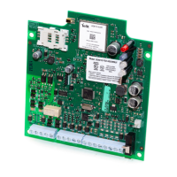
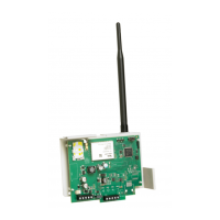
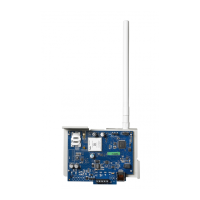
3G Cellular
Transmitter
3G4010
T1/R1
TIP/RING
Zone PGM4
Inputs Output
3G4010 cabinet
3G (HSPA) or
2G (GPRS)
AC Input
PSTN
NOTES:
l Power for 3G4010 shall be provided from Fire Alarm Control Unit or separately listed power supply rated for the applic-
ation, 12V/700mA.
l All wiring connections must be run in a protective conduit.
l For local supervision of the wireless transmitter connect PGM output from 3G4010 to one zone input on the Fire Alarm Con-
trol Unit.
l Dry ContactTrouble output from ULC Listed Fire Alarm Control Unit mustbe connected to zone input on the 3G4010 for
supervision of Tip/Ring connection.
l Fire Alarms mustbe sent over both communication channels.Fire output from Fire Alarm Control Unit must be connected
to the Input 1 on the 3G4010.
l 24h Test Transmission mustbe enabled on the dialler and on the 3G4010.
Figure 7: DSC Subscribers’ Unit Fire and 3G Transmitter Mounted in the Same Room
DSC
Subscribers’
Unit Fire
Zone
Inputs TIP
TIP RING
PGM1
DSC Keypad
LCD4501
PK55XX
3G Cellular
Transmitter
3G4010
T1/R1
TIP/RING
Zone
Input PGM4
AUX Power
12V/700mA
RM1C ULC
Relay
PC5003C
PC4050CR
cabinet
3G (HSPA)/2G (GPRS)
PSTN
AC Input
AC Input
PC4020
PC1864
PC1832
PC1616
RM1C ULC
Relay
3G4010 cabinet
Outputs
Fire
Supervisory
Trouble
Fire Alarm Control Unit
NOTES:
l Power for 3G4010 must be provided from Fire Alarm Control Unit or separately listed power supply rated for the applic-
ation (12V/700mA).
l All wiring connections must be run in a protective conduit.
l Phone Line Monitoring (TLM) must be enabled.
l Phone Line trouble is indicated by Blue LED on 3G4010.
l Connect PGM4 output from 3G4010 (Trouble Conditions) to a zone input on the Subscriber Unit for supervision of the
GSM Transmitter.
l 24hr Test Transmission over phone line (PSTN) and 3G4010 mustbe enabled.
l Fire Alarms mustbe sent over both communication channels.
l On the Subscribers’ Unit, program PGM1 for PC1616/PC1832/PC1864 as System Event (Section [009] as type 10; Sec-
tion [501] Fire Event option 2 ON). An alternate option is to program PGM1 as ZoneFollower (Sec [009] = 29) and assign
Fire Zone to PGM1in Section [551]. Ensure Bit 3 is on in [501]. In this case,a restored fire alarm condition does not require
the DSCcontrol panel to be reset.For PC4020 program PGM1 as type 49 Steady Fire ([00070049]).
l Dry contact outputs from ULC Listed Fire Alarm Control Unit must be connected to zone inputson the ULC Listed DSC Sub-
scribers’ Unit Fire.
l Refer to detailed diagramsin Figure 7.
21