3
Before leaving the installation site, the equipment shall be connected via an APPROVED (acceptable to the local authori-
ties) Network Interface Device (NID). All wiring shall be performed according to the local electrical codes.
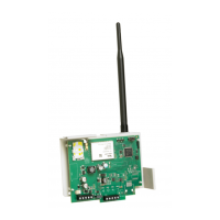
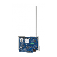
Installing GS2060/TL260GS Communicator with PC1616/1832/1864
NOTE: Before installing the GS2060/TL260GS or inserting/removing the SIM card, ensure that system power is OFF.
1. To assemble mounting bracket, perform the following (See Figure 1).
a. Remove the 4 white plastic standoffs from the
bag provided with the Communicator kit.
b. Insert the 4 standoffs through the back of the sup-
plied mounting bracket, into the holes at each cor-
ner. (The antenna mounting tab should be facing
away from you).
c. Place the bracket on a flat, solid surface. Hold the
Communicator face up and orient the four holes on
the Communicator with the four standoffs protrud-
ing from the bracket. Push the Communicator
firmly and evenly onto the standoffs until it is
securely attached to the mounting bracket.
d. Remove the alarm panel front cover.
e. Remove and discard the circular knockout located
in the top-right section of the panel. (This hole will
be used for connection of the supplied radio
antenna).
f. Connect the supplied 12.7cm (5”) antenna cable to the radio, by passing the connector through the hole on back of the
mounting bracket to the Communicator board. Push the antenna connector firmly into the socket on the GSM
radio.(See Figure 3).
g. Place the nylon washer with bushing (thick flat washer) onto the threaded
section of the antenna cable. Insert the threaded section through the
antenna mounting knockout hole. Place the second nylon washer (flat), fol-
lowed by the brass washer and the brass nut, onto the threaded section of
the cable, outside the panel. Tighten the assembly by hand only. Do not
overtighten the assembly.
2. To install the Communicator module into the panel. (See Figure 3).
a. Attach one end of the PC-LINK cable to the panel PC-LINK header on the
panel (red wire goes on Pin 1 of the panel PC-LINK header.)
NOTE: Note that on the panel, the black wire is on the right, whereas on
the Communicator this is reversed. See Figure 3.
b. Insert the assembled Communicator into the panel cabinet.
NOTE: Ensure that the threaded antenna connection point is visible
through the knockout hole of the panel.
c. Locate the screw hole in the right side wall of the panel. See Figure 2 (i).
Line up the assembled Communicator with the side wall of the panel and,
using the screw provided, secure the mounting bracket to the panel.
d. Attach the supplied white quad band whip antenna to the threaded antenna
connection point at top of the panel.
3. Wire the Communicator to the panel, perform the following (See Figure 3):
INSTALLING THE GSM/ETHERNET COMMUNICATOR
DG009352
Brass Washer
Nylon washer (flat)
Nylon Washer
with bushing
(thicker flat washer)
Brass nut
Antenna
Mounting Tab
Mounting
Holes
Mounting Holes Antenna
Cable
Figure 1 Communicator Mounting Bracket
DG009158
PC-Link Cable Connector
(i)
Figure 2 PC1616/1832/1864 Control Panel
Figure 3 GS2060/TL260GS Wiring Diagram
DG009391
AUDIO/DEFAULT
DSC
UA557
PC-LINK
PC-LINK
GND
PWR
PWR GND GND
SHLD
TL260GS / GS2060
AC AC RED BLKYEL GRN Z1 COM Z2 Z3 COM Z4 Z5 COM Z6 Z7 COM Z8
AUX+ BELL+
AUX-
BELL-
PGM1 PGM3
EGND
TIP T-1
PGM2 PGM4
RING R-1
PC1616/1832/1864
GSM Radio
SIM Card
Holder
+
-
WARNING! All connections to the
TL260GS/GS2060 module are power
limited. Do not route any wiring over the
circuit boards. Maintain at least 1”
(25.4mm) separation between circuit
board and wiring. A minimum of 1/4”
(7mm) separation must be maintained at
all points between non-power limited
wiring and power limited wiring.
UA503
NOTE: For more details, refer to the
control, panel Installation Manual.
1
1
CON 4
To external
antenna
Network Connection
(Model TL260GS)
Use only CAT5 cable
(300ft/100m max.) Supervised
Input Ratings (from Bell Out)
11.1V - 12.6 V
DC
100mA standby; 400mA Alarm
DSC Panel minimum
power requirements
16 V
AC 40 VA transformer
12 V
DC 7Ah battery
Status
LEDs
External Bell/Siren
Black
Black
Hardware
Default
L
o
c
k