10
HSPA(3G) Alarm Communicator Installation Manual
e. Locate the screw hole on the right side wall of the
panel. See Figure 2 (screw). Line up the assem-
bled communicator with the right side wall of the
panel and, using the screw provided, secure the
mounting bracket to the panel.
f. Attach the other end of the PC-LINK cable to the
communicator (red wire goes on the right-hand pin
of the communicator PC-LINK header (see Figure
3)).
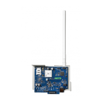
g. Using light pressure (finger tight only), attach the
supplied white quad band whip antenna to the
threaded antenna connection point at top of the
panel.
WARNING! - 3G2080(R)/TL2803G(R) modules are
power limited. Do not route any wiring over the cir-
cuit board. Maintain at least 1in. (25.4mm) separa-
tion between circuit board and wiring. A minimum
of ¼ in. (7mm) separation must be maintained at
all points between non-power limited wiring and
power limited wiring.
3. To electrically connect the communicator to the panel, perform the following steps (See
Figure 3).
a. Disconnect both AC power and battery connections from the panel, and disconnect tele-
phone line.
b. Confirm that the SIM card is inserted in the holder and locked.
4. Install Network Cable (TL2803G(R) only). Route the CAT 5 Ethernet cable through the back of
the panel and plug it into the communicator’s RJ45 jack.
NOTE: Before leaving the premises the Ethernet communication lines must first be connected to
an approved (acceptable to local authorities) type NID. All wiring shall be performed
according to the local electrical codes.
PC-Link
cable connector
screw
quad band
whip antenna
GSM Radio
RJ-45
UA601
Use light pressure
to attach antenna
nger tight only.
HS2016/2032/2064/2128
Figure 2:HS2016/2032/2064/2128 Control Panel
Figure 3:Communicator Wiring Diagram
AUDIO/DEFAULT
DSC
UA601
PC-LINK
COM
TL2803G(R)
3G2080(R)
AC
AC
Z1 COM Z2 Z3 COM Z4 Z5 COM Z6 Z7 COM Z8
AUX+
BELL +
PGM1 PGM3
RING
T-1
HS2016/2032/2064/2128
3G Radio
UA621
To external antenna
Input Ratings:
+10.8V ~ +12.5 VDC
90mA(3G2080(R))/120mA(TL2803G(R)) standby;
400mA alarm
DSC Panel min. power requirements:
- 16.5 VAC 40 VA transformer;
- 12 VDC 7Ah battery
Jumper pins 4 and 5
to reset.
L
o
c
k
1
From NID
TL2803G(R)
Use only CAT5
Supervised
RJ-45
GRN
YEL
TIP
R-1
BLK
RED
AUX -
BELL -
EGND
TX+
GND
TX-
RX+
RX-
SHLD
SIM
Network Link
YELLOW
PGM2 PGM4
Maximum cable length
100 m (328 ft)
PCLINK_2
Red
Red
RS-422
To 3rd party device