SLICE User’s Manual July 2017
support.dtsweb.com 57 Version 1.0i
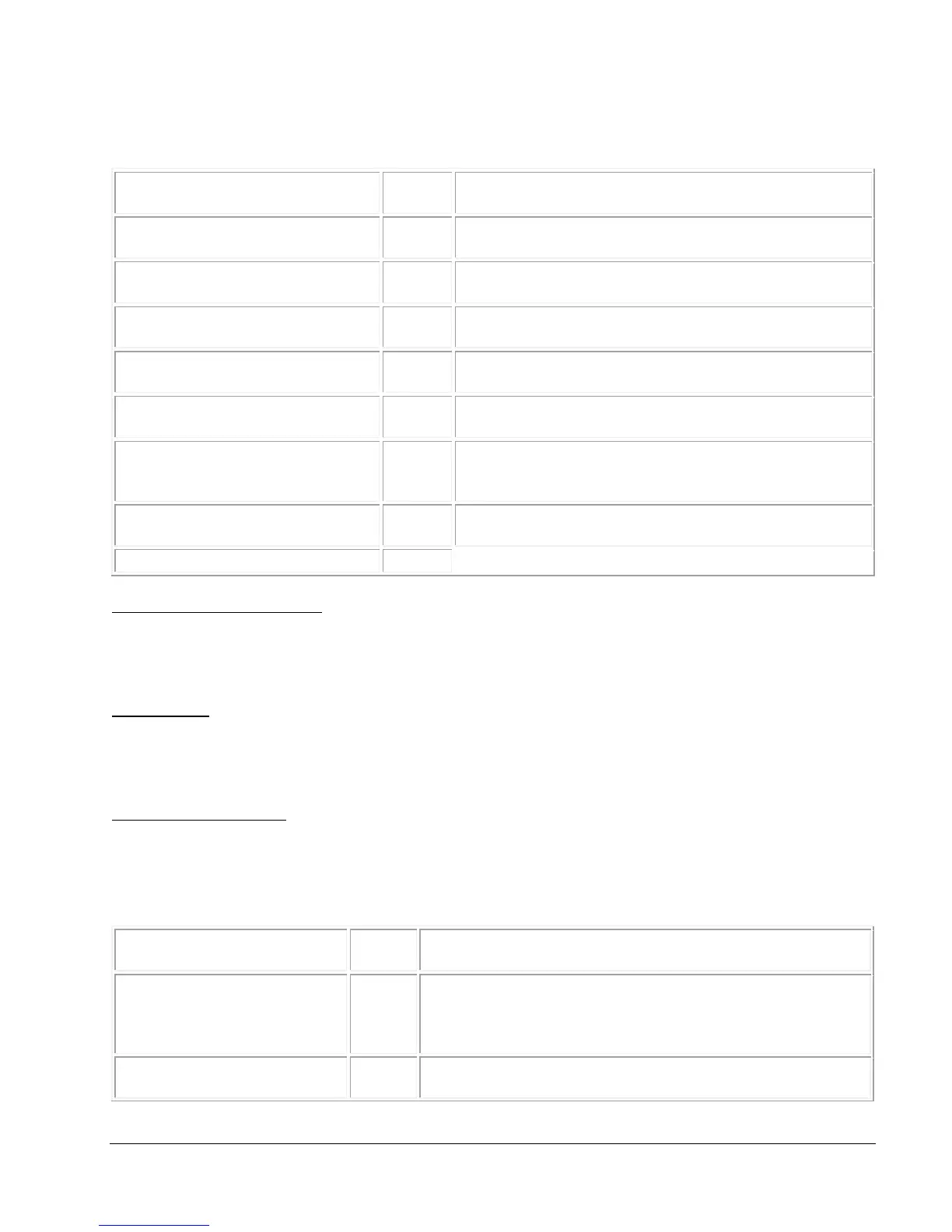
UnsubsampledNumberOfSamples
The total number of samples collected during data
acquisition
The number of seconds of recorded data that the
user requested after t=0
The number of seconds of recorded data that the
user requested before t=0
Either the value RecorderMode or CircularBuffer.
Other values will be added in the future.
The rate at which sampling occurred during data
collection
The sample number at which the start signal was
first detected. The value will always be 0 when
RecordingMode=CircularBuffer.
The number of user configured channels within the
module
<TriggerSampleNumbers>
This is a list (possibly 0 length) of trigger sample numbers. In the circular buffer case, there will
be one trigger sample number. In recorder mode, the trigger is optional. In the case of
multiple event mode, there may be more than one trigger sample number.
<Channels>
The Channels tag contains a list of channel elements. It should have the same number of
entries as NumberOfChannels in the Module tag. The type of the child elements will depend on
the type of signal conditioning SLICE used.
<AnalogInputChanel>
The AnalogInputChanel tag corresponds to a Bridge SLICE channel. (Note: There is a typo in
the tag name and “Chanel” is misspelled. It has been retained for backward compatibility.)
Many of the attributes indicate how the channel was configured during the test. The
AnalogInputChanel element has the following properties:
This identifies the representation of the data contained
in the .BIN file. Currently this value is always expected
to be
DTS.Serialization.Test+Module+AnalogInputChannel.
The channel number within the signal conditioning unit.
In a Bridge SLICE, channels are numbered 0–2.