21
4.4 CONNECTING TO THE ELECTRICITY MAINS
The lift must be connected to the mains electricity supply by the customer.
To connect to the electricity supply, use a 3 core + earth cable with cross section of 2.5 mm2 for the 380V version;
To connect to the electricity supply, use a 2 core + earth cable with cross section of 2.5 mm2 for the 220V version
The cable must be completed with a main plug of the type in use in the country where the lift is installed.
The lift is fitted for the mains connection cable to arrive from below, but it can also be received from above.
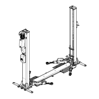
THREE-PHASE CONNECTION
Once the passage of the cable has been carried out, it must be suitably stripped, the ends of the unsheathed wires
and provided with insulating bushings and the appropriate yarns R, S, T, and PE.
It should be remembered that the presence of the PE marking machine is expressly provided for by the electrical
regulation EN60204 and therefore it is absolutely necessary to provide for its application.
The conductors must be connected as shown in the diagram figure 14:
The phase conductors R, S, T to the terminals of the QF differential switch, while the PE ground conductor is
connected to the special ground rod.(figure 15)
The machine operates normally at 400 Volt 50 Hz (Star). The actual supply voltage is indicated on the identification
plate.
The electrical system and the connections are different according to the supply voltage / frequency and are set up
in the factory.
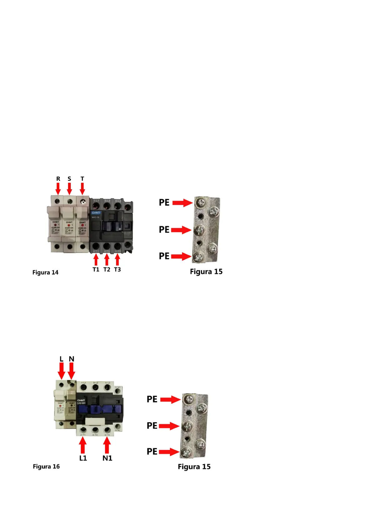
MONO-PHASE CONNECTION:
Once the passage of the cable has been carried out, it must be suitably stripped, the ends of the unsheathed wires
and provided with insulating bushings and the appropriate yarns L, N, PE.
It should be remembered that the presence of the PE marking machine is expressly provided for by the electrical
regulation EN60204 and therefore it is absolutely necessary to provide for its application.
The conductors must be connected as shown in the diagram figure 4a:
The phase conductor L and the neutral N at the terminals of the differential switch QF, while the PE ground
conductor is connected to the special ground rod.
Connect the cables coming from the motor on the terminal board in position L1 and N1