27
4.9 CHECK THE MOTOR ROTATION
DIRECTION
Then lower the lift using the down button [12] switch on the control panel. The carriages must descend
simultaneously. If the carriages run in the opposite direction to that set using the selector switch, swap two wires
inside the power supply cable plug.
WARNING
The motor rotation direction must be checked whenever the lift’s power source is changed.
4.10EXHAUSTING OF HYDRAULIC SYSTEM OF LIFT
There will be air in hydraulic system in new installation, exhausting is necessary. When connecting pipes, the
cylinder should be in lowest position with smallest air cavity, and then press ‘up’ button to lift to the maximum height,
and stop for 10-15seconds, the pressure for hydraulic system will reach the maximum now so the relief valve opens
automatically and then the air passes through the hydraulic system and form the circuit. And then press ‘down’
button to lower the lift to minimum height. Repeat the up and down procedures above 2 or 3 times to complete the
exhausting.
If the raising-of truss is not enough in the installation spot and the lift cannot reach to maximum height, lift the
machine to a certain height and loosen the cylinder joint manually to exhaust. When the air is drained, re-tighten
the cylinder joint.
ATTENTION:
exhausting for hydraulic system of lift is very important, otherwise it will affect the lift to work
properly. Do apply the procedure after installation.
5 – INSTRUCTIONS FOR USE
5.1 START UP
WARNING
The lift must be put into service by specially trained personnel, in order to assure the correct functioning
of the lift itself and all its mechanical and electrical safety systems.
The instructions to be followed are provided in the final section of this manual, for the use of the technicians who
carry out the start-up procedure only.
No work on the part of the staff that does not belong to the after-sales service of the manufacturer must be
permitted.
WARNING
The manufacturer declines liability for any damages resulting from failure to follow the above instructions,
which may invalidate the warranty.
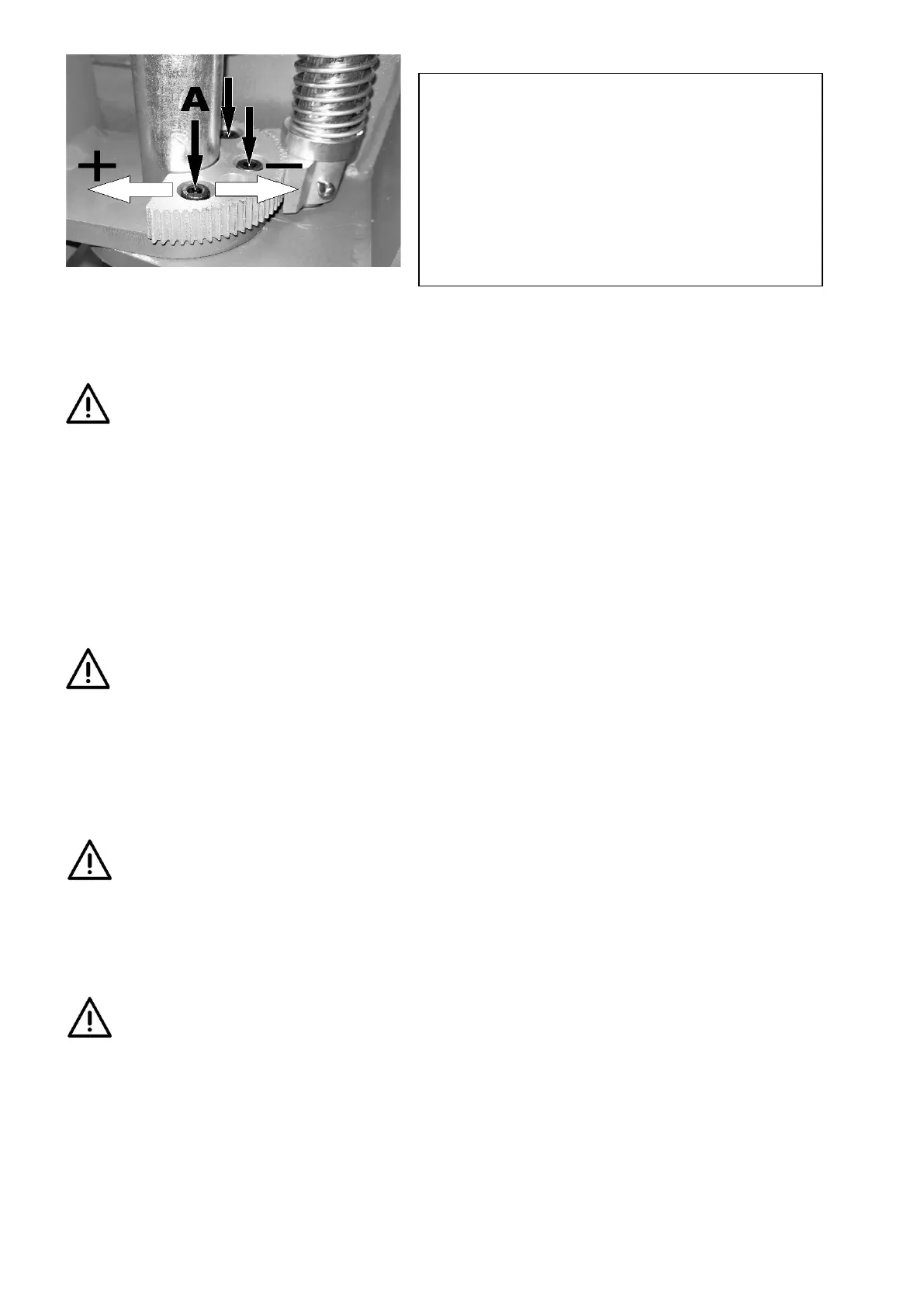
Adjustment of the arms looking
Unscrew the screws A (see picture).
near to the pin (marked-) or move away (marked +) until the gear
engages properly.
After adjustment, tighten the screws A.