25
4.7 HYDRAULIC CONNECTION
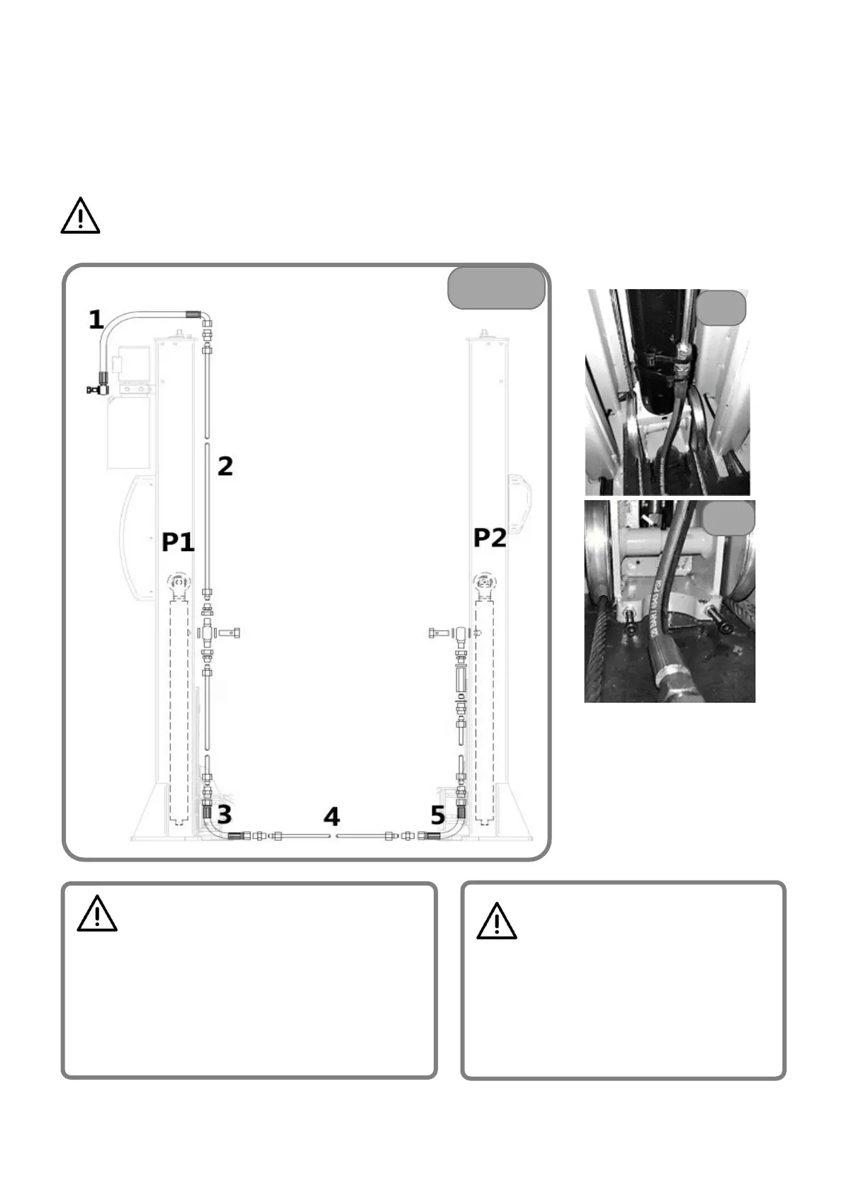
The lift is partially assembled in the hydraulic part.
To complete the hydraulic connection:
• First position the fixing pipe[4] and fix the pipe to the place between the two flexible oil pipes[3] and [5] from
pillar 1 and pillar 2, as shown in FIG.5;
• And then position the fixing pipe[2] and fix it to the middle of fixing oil pipe[3], as shown in Figure 5;
• Finally position the hydraulic pump and connect it to the top of pillar 1, and connect one side of flexible oil pipe
[1] to the joint of iron oil pipe[2] and fix the other side through fitting bolt to the valve plate of the pump;
ATTENTION: when connecting oil pipes, please use two wrenches to fix to avoid leakage
caused by untightened fixing.
WARNING
Ch
eck that there are no oil leaks, if necessary,
switch off the voltage and tighten the loose
hydraulic connections.
The lift to work requires ISO VG32 viscosity hydraulic
oil not supplied. (Optional).
Unscrew the oil filler cap and insert 9 liters of hydraulic
oil into the tank.
ATTENTION
When connecting iron oil pipe [4], pay
attention to the place of flexible pipe [3]
and [5], for any offest, please refer to the
position of oil pipes in figure 5a and 5b, to
fix the pipes in case that, when the carriage
goes down to the bottom, it will intervene